This week we did our last iteration on Shootah and added a Bomb to be dropped by the enemy to try to hit the player.
Bomb Class
We copied the existing Bullet class and called it Bomb instead. The main changes we had to make were:
Changing the speed to a negative number so that it moved down instead of moving up (as the Bullet does)
Changed the check for the top of the screen to one for the bottom of the screen instead (to account for the fact it moves down)
Changed the check in its hit() function so that the Bomb doesn’t interact with the Enemy when it’s dropped, but will be marked as inactive it if hits anything else.
Changed the colour of the bomb to red
ManagesBombs
It happened that the code we had already written to manage bullets was already perfect for managing bombs as well.
We used Visual Studio Code’s built-in capability to automatically rename symbols to:
Rename the bullets array to projectiles
Rename the manageBullets() function to manageProjectiles()
This was enough to have bombs move, draw and be removed when it becomes inactive.
Dropping Bombs
We added a new function to Ememy called shoot(). In that function we generated a random number from one to two hundred. We then dropped a bomb every time that number was less than five (we tuned this small number to get a good rate of bomb drops). This meant that the enemy dropped a bomb at random intervals, to make it impossible for the player to anticipate.
Download
The files for this week can be found on our GitHub repository.
A special welcome to all our new members that came to us this week, I hope you enjoyed yourself and hope to see you back again soon.
Thank you all for coming again this week. This week we looked at pen commands, we have not done this before in the Explorers group so it was new for everyone.
We also created some variables which we set as sliders which again is something we had not done before with this group.
This week we extended our colliders so that we could used them to prevent the player going off the edges of the screen. We used it to show how software design needs to evolve.
Colliders
Our colliders were designed to be connected to an object with three things:
A property x containing the x-coordinate of its location
A property y containing the y-coordinate of its location
A function hit() which was called if the attached collider touched another collider
Something to Connect To
We had colliders already attached to our:
Enemy
Bullets
but we didn’t have anything to attach to that could represent the side of the screen.
We created a new class called Static() with nothing more than the x, y and hit() that we needed so that we could connect a collider to it (stored in one more property – collider).
Screen Edges
We created a pair of these colliders positioned at the right and left-hand side of the screen. We made sure to add them to our list in check_colliders(). Nothing much happened. Why? Well, first, the Player didn’t have a collider, so we added one, liberally copying code from Enemy, which a minor change to the description argument.
Now we could see the contact occurring between the edge and the player, though nothing was stopping it moving yet.
Unintended Consequences
As often happens with code, this change had unexpected consequences; bullets were not firing properly any more. Why? Because the player now had a collider and the bullets were becoming inactive immediately because they were hitting that. The fix was to modify the Bullet’s hit() function to ignore hitting a collider with the description “player”.
Stopping the Player Moving
We now knew our player was hitting an edge, but another problem became apparent: we didn’t know which edge!
To properly stop the player and stop it moving too far, we really needed to know which side of the player the collider we’d hit was, but that information wasn’t available to us with the current design.
A couple of quick changes were necessary:
In Collider.touching(), instead of just passing the descriptors to the objects hit() functions, we changed it to pass the Collider itself.
In all the hit() functions, we had to made a small adjustment to account for the fact that we were now getting a Collider and not just a string.
With the extra information from the collider, were were able to determine how far the player should be allowed to move to and prevent it going further by setting the x value appropriately.
Download
The files for this week can be found on our GitHub repository.
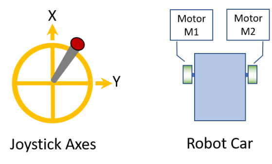
We have a robot with two wheels attached to motors, one on the left and one on the right
We have code to control the motors for the two wheels (which we call MotorM1 and MotorM2) with a value in the range -1 to 1, where 1 is full speed ahead, 0 is no movement, and -1 is full speed reverse
We have a camera mounted on the robot, facing directly ahead
We have code to get an image from the camera and can detect an object of interest, and find its centre (or centroid) within the image
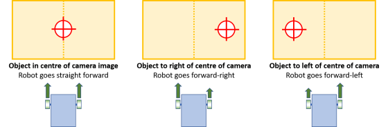
The objective is:
If the object is in the middle of the image, robot should go straight ahead (M1=1, M2=1)
If the object is to the right, move forward-right (e.g. M1=1, M2=0.7)
Likewise, if the object is to the left of centre, move forward-left (e.g. M1=0.7, M2=1)
If the object is not found, we turn the robot around in a circle to search for it (M1=1, M2=-1)
The first three of these are illustrated below:
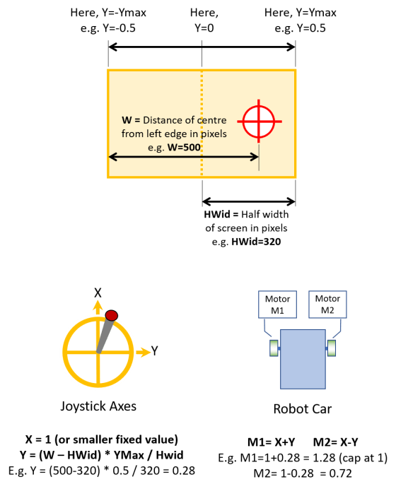
Our solution is to treat this as a variant of what we previously worked out before, where we had a joystick input, where the X direction of the joystick controls forward movement and its Y direction controls whether to move left or right. In this case, we are steering left/right while always moving forward. Therefore, X has a fixed value (X=1) and Y is a value that depends on the direction of the object of interest.
The equations we came up with are:
X = 1 (a fixed value)
Y = (W – HWid) * YMax / HWid
Then use X and Y to calculate the motor control values as before:
M1 = X + Y, constrained to being between -1 and +1
M2 = X – Y, constrained to being between -1 and +1
Here:
X is a fixed positive value: X=1 for full speed, or make it smaller to move forward more slowly
Y is calculated from the equation above
W is the distance of object’s centre from left edge of the image, in pixels
HWid is half the width of the image, in pixels (for example, for a basic VGA image, 640×480, HWid is 640/2 = 320)
YMax is a value approximately 0.5, but needs to be calibrated – it depends on how sharply you want your robot to steer towards the object
M1 is the control signal for Motor M1, in the range -1 (full reverse) to +1 (full forward)
M2 is the same for Motor M2
Constrained means: if the calculated value is less than -1, set it to -1; if it is greater than +1, set it to +1.
At our most recent session in the Hackers group in CoderDojo Athenry, we spent out time on practical mathematics, figuring out how, if we want to make a robot that is controlled by a person with a joystick, how exactly do we translate movements of the joystick to signals sent to the motors.
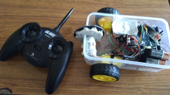
Our assumptions are:
We are controlling robot with 2 drive wheels, one on the left and one on the right, like the one shown in the photo above (which we made last year)
We assume that we have code to control the motors for the two wheels (which we call MotorM1 and MotorM2) with a value in the range -1 to 1, where 1 is full speed ahead, 0 is no movement, and -1 is full speed reverse
To make the robot turn, drive the motors M1 and M2 at different speeds
We assume that we have code to receive signals from the joystick, and get X and Y values in the range -1 to 1, as shown in the diagram below
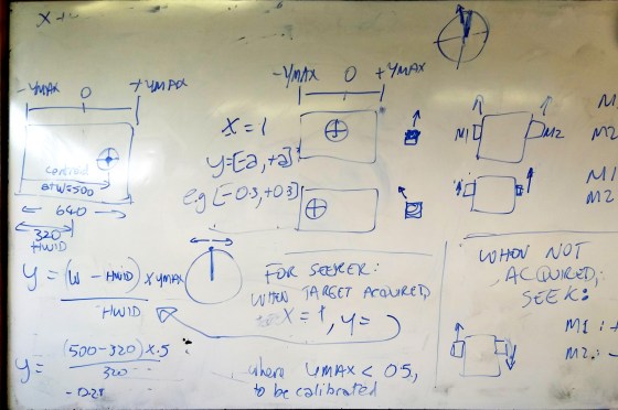
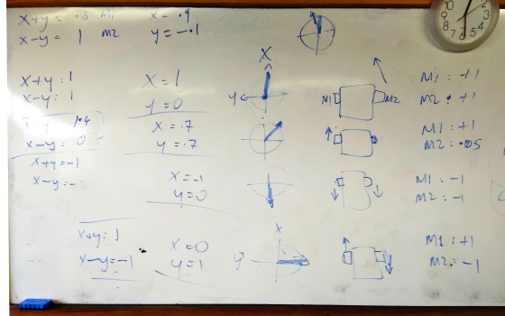
Our approach was to think about what joystick positions (X and Y) should result in what robot movements (M1 and M2), and then see if we could come up a way of expressing M1 and M2 in terms of X and Y. We filled a whiteboard with satisfying diagrams and calculations; see the bottom of this post. I have re-dawn them for clarity below.
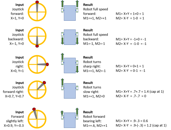
The resulting equations are quite simple:
M1 = X + Y, constrained to being between -1 and +1
M2 = X – Y, constrained to being between -1 and +1
Here:
M1 is the control signal for Motor M1, in the range -1 (full reverse) to +1 (full forward)
M2 is the same for Motor M2
X is the forward position of the joystick from -1 (full back) to +1 (full forward)
Y is the left/right position of the joystick from -1 (full left) to +1 (full right)
Constrained means: if the calculated value is less than -1, set it to -1; if it is greater than +1, set it to +1.
Here is the full set of joystick positions and motor movements that we considered, showing how the equations work:
Each motor needs two control signals in the range 0-255, one for forward and one for reverse, so we will need more code to convert our M1 and M2 to what is needed for the H-bridge, but that is a fairly easy job for a different day.
This week we mainly dealt with building and using a box collider in our game. The box colliders are written in a way such that:
They are connected to something in the game and follow it around
What they are attached to must have the properties x and y for position
It is possible to test if they are touching each other
If two colliders are found to be touching, we tell the things that they’re attached to that they’ve been hit by something
What they are attached to must have a function hit() that we can call
Extents of the Collider
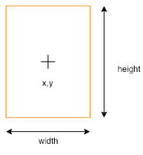
Our collider is a box, of a given width and height, centred on the x and y of the thing it’s connected to:
For checking collisions, we need to know the x values of the left and right side of the box and the y values of the top and the bottom of the box.
For convenience, we write a function which returns an object (using curly brackets) with the left, right, top, and bottom values (shortened l, r, t and b respectively) as properties:
When making an object like this, we set a property value by first writing the property name, followed by a colon (:) and then a space and the value we want it to have. Each property is separated with a comma. The don’t need to be on separate lines, but it makes it easier to read.
Touching Colliders
So how do we know that two colliders are touching? Actually there are four ways in which they definitely can’t be touching:
One is completely to the left of the other
One is completely to the right of the other
One is completely above the other
One is completely below the other
And if none of these are true, then it must be touching. So actually, we’re going to check that they’re not NOT touching (double negative, used correctly!).
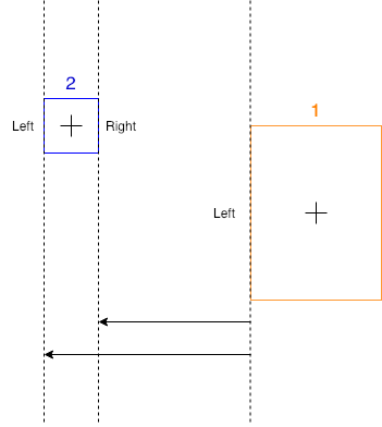
How do we know if something is completely to the left of something else? Look at this diagram:
We know that box 2 (in blue) is totally to the left of box 1 (in orange) because we can see it is, but how could get the computer to check it? Remember, left and right are just x values on the screen. Box 2 is left of box 1 because both it’s left and right values are smaller than the left value of box 1.
The checks for the other directions are very similar:
The second box is right of the first box when both of it’s x values (left and right) are greater than the first’s right side.
The second box is above of the first box when both of it’s y values (top and bottom) are less than the first’s top side.
The second box is below of the first box when both of it’s y values (top and bottom) are greater than the first’s bottom side.
Sending Messages
Each collider has a property disc that describes the thing, or type of thing, that it’s connected to.
All colliders know what they’re connected to, so when we determine two have touched, we call a function called hit() on each of the connected objects, passing it the desc of the other collider. This means, in our game, when our enemy is hit, it can know that it’s been hit by a bullet – or maybe something else – and react appropriately.
Checking Every Collider Against Every Other
In our code, we gather all the active colliders at each frame. We then need to check each one against each every other one. How can we do that?
Consider a list of four items:
To check them all against each other we first need to check 0 against the other three. Simple enough.
We we need to check 1. But we don’t need to check 1 against 0, since we already did that. Nor do we need to check it against itself. We only need to check it against 2 and 3.
If we write out the full sequence, we see that for four items we need three passes to check all combinations:
First pass: Check 0-1, 0-2, 0-3
Second pass: Check 1-2, 1-3
Third pass: Check 2-3
We can write a pair of loops to do this:
for (let i = 0; i < c.length - 1; i++){
  for (let j = i + 1; j < c.length; j++){
    c[i].touching(c[j]);
  }
}
Note two things about these loops:
The first loop goes from zero, but stops one short of the last item in the list (i < c.length – 1). It picks the first item to be checked.
The second loop doesn’t start from zero. It starts from what ever i currently is, plus one. It picks the second item to be checked.
Other Stuff
We also did a few other things this week:
We fixed a small bug that was keeping our spaceship moving when we didn’t want it.
We added a little drag to slow the spaceship down to a stop when we lift our fingers off the keys
We set bullets inactive when they hit something
Download
The files for this week can be found on our GitHub repository.
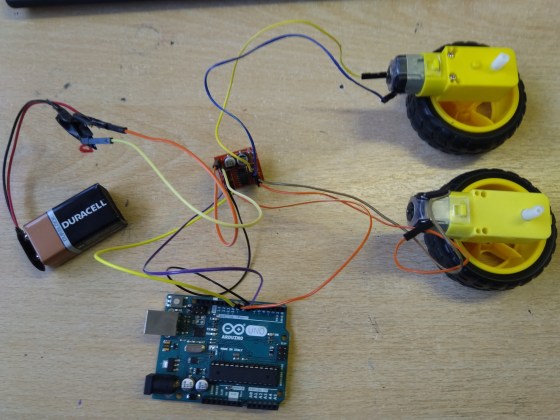
Last week, we figured out how to control a motor with a H-bridge. We expanded this to controlling a pair of wheels using the H-bridge. Above is a photo of the hardware. The wiring of the H-bridge is:
H-bridge [+] and [-] are connected to a 9V battery
H-bridge [IN1] to [IN4] is connected to Arduino Pins 6, 7, 8, 9
H-bridge [Motor A] and [Motor B] pins are connected directly to the two motors
Below is Arduino code by Hackers member Luke to control this.
// Luke Madden, CoderDojo Athenry
// Control motors using a H Bridge

// The H bridge has 4 input pins: in1-in4
#define in1 6
#define in2 7
#define in3 8
#define in4 9

int fast = 150;// range 1-255
int slow = 80;// slower speed
int hyperspeed = 255;// hits the hyperdrive

void setup() {
  pinMode(in1, OUTPUT);
  pinMode(in2, OUTPUT);
  pinMode(in3, OUTPUT);
  pinMode(in4, OUTPUT);
  Serial.begin(9600);
}

void loop() {
  drive();
}

 void drive() {
  // Test the functions
  Serial.println("move forward");
  forward();
  delay(2000);

  Serial.println("hit the hyperdrive");
  hyperdrive();
  delay(2000);

  Serial.println("go backwards");
  backwards();
  delay(2000);
}

void forward() {
  //makes motor go forwards
  analogWrite(in1, fast);
  analogWrite(in2, 0);
  analogWrite(in3, fast);
  analogWrite(in4, 0);
}

void hyperdrive() {
  //hits the hyperdrive
  analogWrite(in1, hyperspeed);
  analogWrite(in2, 0);
  analogWrite(in3, hyperspeed);
  analogWrite(in4, 0);
}

void backwards() {
  //makes motor go backwards
  analogWrite(in1, 0);
  analogWrite(in2, fast);
  analogWrite(in3, 0);
  analogWrite(in4, fast);
}

void stopping(){
  //makes it stop
  analogWrite(in1, 0);
  analogWrite(in2, 0);
  analogWrite(in3, 0);
  analogWrite(in4, 0);
}
Handling Interrupts in Arduino
In Arduino, you can set up special functions that are a called depending on the state of some digital pins – these are called Interrupt Service Routines (ISRs). These routines are called separately from the main loop() that is always running, even if the main loop() is in the middle of another operation.
For controlling our robots, our Arduino might receive a signal on a pin, and if we want the robot to react quickly, an ISR can handle it. The ISR can send a signal on a different pin or change the state of a variable.
This code is simple and correctly-working demonstration of how interrupts work. Note that you don’t need to build any circuitry to try this out. A built-in LED on the Arduino, at pin 13, turns on/off depending on whether Pin 2 is connected/disconnected from the the GROUND pin.
There are three main tasks:
Define the ISR function: this is a function declared as void with no arguments: for example, our ISR is called changed and is defined as:
void changed() { … }
In our code, it sets the value of a variable called controlState and it turns the LED on/off. Note that the value of controlState is printed out repeatedly in the main program loop, showing how the ISR can change a variable that is used elsewhere.
In the setup() function, set the pin mode of the control pin to INPUT or INPUT_PULLUP (see below for the difference). For example, we have defined the variable control to have value 2 and are setting its mode like this:
pinMode(controlPin, INPUT_PULLUP);
In setup(), attach the ISR to the pin:
attachInterrupt(digitalPinToInterrupt(controlPin), changed, CHANGE);
One extra note about the above line of code: all pins have numbers and all interrupts have numbers, and these are not (necessarily) the same numbers. The function digitalPinToInterrupt() returns the interrupt number corresponding to a given digital pin.
Some other things to note:
The Interrupt Service Routine (ISR) should be short and run fast: delay() calls are ignored and print() can cause problems.
You can’t attach two interrupts to the one pin: use CHANGE and then test pin state
If you initiate the pin with INPUT_PULLUP, it is triggered by connecting it to GROUND; otherwise, if you initiate it with INPUT, you need a circuit with 10k resistor.
On an Uno, can only attach interrupts to pins 2 and 3.
If you are changing a variable in the ISR and need to use it elsewhere, declare it as volatile.
Here is the full Arduino code:
// Michael Madden, CoderDojo Athenry
//
// Test a pin interrupt to which an interrupt service routine (ISR) is attached.
// When the control pin is connected to GROUND, the LED on the board is turned on.

// Things we have figured out:
// * The interrupt service routine (ISR) is a function declared as void with no arguments.
// * It should be short and run fast: delay() calls are ignored and print() can cause problems.
// * You can't attach two interrupts to the one pin: use CHANGE and then test pin state
// * If you initiate the pin with INPUT_PULLUP, it is triggered by connecting it to GROUND;
// * otherwise, with INPUT, you need a circuit with 10k resistor.
// * On an Uno, can only attach interrupts to pins 2 and 3.
// * If you are changing a variable in the ISR and need to use it elsewhere, declare it as volitile.

const byte controlPin = 2; // Want to react when this pin is triggered
const byte ledPin = 13; // no circuit needed: there is a built in LED on 13
volatile int controlState = 0; // will change this value in ISR

void setup() {
  pinMode(ledPin, OUTPUT);
  pinMode(controlPin, INPUT_PULLUP);
  attachInterrupt(digitalPinToInterrupt(controlPin), changed, CHANGE);

  Serial.begin(9600);
}

void loop() {
  // The main loop does not do much, it just prints out the value of the
  // control pin's state every 2 seconds.
  Serial.print("Current value of control pin = ");
  Serial.println(controlState);
  delay(2000);
}

void changed()
{
  // This is our interrupt service routine.
  // It is triggered when the control pin changes,
  // so we check its state and turn on/off the LED.
  //
  controlState = digitalRead(controlPin);
  if(controlState > 0) {
    digitalWrite(ledPin, HIGH);
  }
  else {
    digitalWrite(ledPin, LOW);
  }
}
This week we continued our Shootah project. We did two main things;
Changed the code to control the total number of bullets to those actually on screen
Added an enemy that loops backwards and forwards across the screen
Controlling the Number of Bullets
In Part 2, we made a new bullet every time the user pressed the Up key and put it in the bullets list.
This meant that after a while we could have a lot of bullets, most off the top of the screen, which was even slowing some machines down.
To limit the number of bullets we did four things:
Added a new property to the Bullet class called active and set it to be true
In the move() function for the bullet class, we added a check for the bullet going off the top of the screen (this.y < 0) and, if true, set the active property to false
In sketch.js, we moved the lines of code in the draw() function responsible for moving and drawing the bullets into a new function called manageBullets() and called it from draw().
In manageBullets() we made a new list called active and put every bullet that was still active into it. We then made this the new bullets list.
We write a little code that printed out the total number of bullets to verify this was working.
Adding an Enemy
We added a new file called enemy.js and included it in the index.html file.
This file looked a lot like player.js. The main different was the move() function. Our enemy moves constantly left-to-right. When it gets too far off the right-hand side of the screen (checked in move()) we set its x position to be off the left-hand side of the screen instead. This makes it loop around.
TODO
We still have loads to do and we made a list on the day:
No more infinite bullets!
Check edges so spaceship doesn’t disappear
Enemies
Collision detection
Enemies shoot back (bombs)
Lives/score
Levels
Background music
Moving background
Story
We’ve done two and we’ll do some of the others for sure.
Download
The files for this week can be found on our GitHub repository.
When you write to a pin on the Arduino, it outputs a voltage. However, you can’t use this directly to drive an electric motor, because they require too much current, and it would damage the Arduino. The solution is to use a 6V battery as an external power supply, and connect it to the motor via a transistor circuit. When you apply a signal with small current to the middle leg of the transistor, a much larger current can flow from the battery to the motor.
While this works, a more elaborate circuit is needed if you want to be able to control two motors, and make them go backwards and forwards. This circuit is called a Dual H-Bridge. The Wikipedia page has technical details: https://en.wikipedia.org/wiki/H_bridge
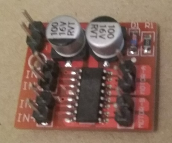
We are using a pre-built integrated circuit for our H-Bridge, as they are low-cost, small, and work well. Here is the one we are using:
It has several connectors:
[+] and [-] are where the external battery is connected
[IN1] and [IN2] control Motor A (details below)
[IN3] and [IN4] control Motor B
[Motor A] and [Motor B] each have two pins that are connected directly to motors
To control Motor A, connect [IN1] and [IN2] to two pins of the Arduino, such as 6 and 7:
[IN1] HIGH and [IN2] LOW: Motor A goes forward full speed
[IN1] LOW and [IN2] HIGH: Motor A goes backward full speed
Both LOW: Motor A does not turn (no power, it coasts)
Both HIGH: Motor A does not turn (is braked)
To control speed, use a value for the pins connected to [IN1] or [IN2] in the range 0-255 (0=LOW, 255=HIGH)
Here is Arduino code to control a motor with a H-Bridge, written by Luke, one of our Hackers:
// Luke Madden, CoderDojo Athenry
// Control motors using a H Bridge

// The H bridge has 4 input pins: in1-in4
#define in1 6
#define in2 7

int fast = 100;// range 1-255
int slow = 50;// slower speed
int hyperspeed = 255;// hits the hyperdrive

void setup() {
  pinMode(in1, OUTPUT);
  pinMode(in2, OUTPUT);
  Serial.begin(9600);
}

void loop() {
  drive();
}

 void drive() {
  // Test the functions
  Serial.println("move forward");
  forward();
  delay(2000);

  Serial.println("hit the hyperdrive");
  hyperdrive();
  delay(2000);

  Serial.println("go backwards");
  backwards();
  delay(2000);
}

void forward() {
  //makes motor go forwards
  analogWrite(in1, fast);
  analogWrite(in2, 0);
}

void hyperdrive() {
  //hits the hyperdrive
  analogWrite(in1, hyperspeed);
  analogWrite(in2, 0);
}

void backwards() {
  //makes motor go backwards
  analogWrite(in1, 0);
  analogWrite(in2, slow);
}

void stopping(){
  //makes it stop
  analogWrite(in1, 0);
  analogWrite(in2, 0);
}