Notes for week 15 covering the importation of lantern and tree into our glade and the start of our moth creation.
Copies of files can be found on our Github.
Notes for week 15 covering the importation of lantern and tree into our glade and the start of our moth creation.
Copies of files can be found on our Github.
Notes for weeks 13-14 covering the creation of foliage, the blended ground texture and distributing the foliage.
Copies of files can be found on our Github.
Notes for weeks 9-12 covering the creation of the lantern, candle, lantern stand and tree.
Copies of files can be found on our Github.
Hi folks,
Below are links to some resources we’re going to use today:
Hi folks, here are the notes for Modelers Week 4, we completed our island scene with materials, lighting and effects.
Copies of files can be found on our Github.
Hi folks, here are some video notes for Weeks 1 & 2 for those who’d like to review what we did, or missed our sessions.
Download and install Blender from here: https://www.blender.org/download/
This week we looked at adding obstacles to our game and detecting collisions.
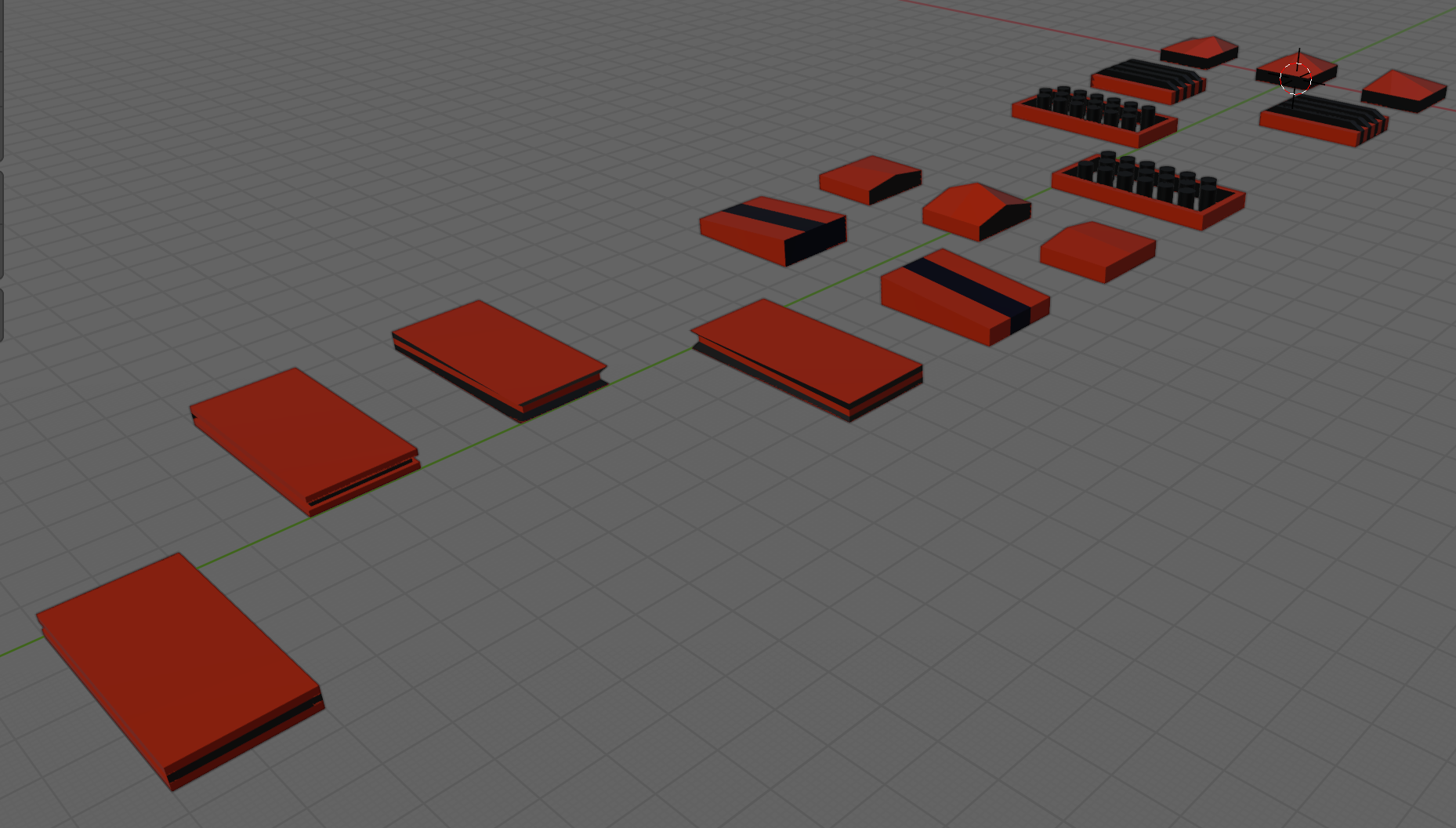
The obstacles were created in Blender and provided as an FBX file. To process them we:
Generally speaking, Unity tracks collisions between objects as long as:
Unity draws a distinction between RigidBody components depending on the setting of “Is Kinematic”. If “Is Kinematic” is false, Unity takes responsibility for moving the object according to physics rules. If “Is Kinematic” is true, we’re responsible for moving the object, but Unity will still track if for collisions, etc. The latter is appropriate for our game.
When Unity detects collision it looks for functions OnTriggerEnter() or OnCollisionEnter() to call, depending on whether the RigidBody is kinematic or not. Ours isn’t so we’ll be implementing OnTriggerEnter() when it’s time to do so.
We added two new public properties to EnvController.cs, one to determine how likely that a piece of environment contains an obstacle and another to hold the prefabs for the obstacles:
  public float ChanceOfObstacle = 0.2f;
  public GameObject[] ObstaclePrefabs;
We then added a new function GenerateObstacles() to EnvController.cs:
  private void CreateObstacle(Vector3 position, Transform transform)
  {
    // Pick a random prefab
    int numPrefabs = ObstaclePrefabs.Length;
    GameObject prefab = ObstaclePrefabs[Random.Range(0, numPrefabs)];

    // Create an instance of it
    Quaternion rotation = Quaternion.Euler(0, -90, 0);
    GameObject go = Instantiate(prefab, position,
                                rotation, transform);

  }
and called it from just before the last line of CreatePrefab():
    // Create obstacle?
    if (Random.value <= ChanceOfObstacle)
    {
      // Create an obstacle as a child of this piece of env
      CreateObstacle(position, go.transform);
    }
We don’t want obstacles at the start because they can lie on top of our ship. Adding a second argument to CreatePrefabs() allows us to control this:
private GameObject CreatePrefab(Vector3 position, bool createObstacles = true)
  {
Because this argument has a default value (= true) and is at the end of the argument list, this makes it optional. If we don’t use it, it’s assumed that we want obstacles.
We can check this value were we create obstacles:
    // Create obstacle?
    if (createObstacles && Random.value <= ChanceOfObstacle)
    {
      // Create an obstacle as a child of this piece of env
      CreateObstacle(position, go.transform);
    }
The double-ampersand (&&) means “and”. Both things have to be true or no obstacles are created.
Finally we modify Preload() so that obstacles are not created when it’s generating the first few environment pieces:
  private void Preload()
  {
    for (int i = 0; i < Count; i++)
    {
      Vector3 pos = Vector3.right * i * Spacing;
      _lastGo = CreatePrefab(pos, false);
    }
  }
To set up the player for collisions, we need to:
With our simple OnTrigger() we can see when collisions are being detected:
  private void OnTriggerEnter(Collider other)
  {
    Debug.Log("I hit something");
  }
All the code we’re made this year is on our GitHub. It can be found here. If you don’t have the latest version of our code before any session, use the green Code button on that page to get the “Download ZIP” option which will give you a full copy of all code we’ll be writing this year.
Please note that there was no Week 14 session as it had to be cancelled owing to bad weather.
When we finished our last session, our EnvController was creating random pieces of environment continuously and scrolling them under the ship. It looked good, but there were gaps between the environment pieces, getting larger the higher we set the environment speed.
Why was this gap happening? Well it’s easy to understand if you look at it this way: if something is moving and you shout stop at a random time, what are the chances that it’s moved some exact distance? Almost no chance of that at all. This is what the current code is doing and why, the faster it’s moving, the larger the gaps get.
The first thing we can do to make this easier is to check more often if the blocks have moved far enough to create a new one. By changing Update() to FixedUpdate() this helps because while Update() is called every frame, FixedUpdate() is called much more often and on a regular timer, independent of frame rate. It’s normally used for physics calculations.
The second thing we can do is to not create our new block at _spawnPoint but to work out the proper position to create it so it’s exactly 100m from the previous one. This is what that code looks like:
void FixedUpdate()
  {
    if (_lastGo == null)
      return;

    float distToLast = Vector3.Magnitude(_lastGo.transform.position -
                                         _spawnPoint);
    if (distToLast >= Spacing)
    {
      Vector3 spawnAt = _lastGo.transform.position + Vector3.right * Spacing;

      _lastGo = CreatePrefab(spawnAt);
    }
  }
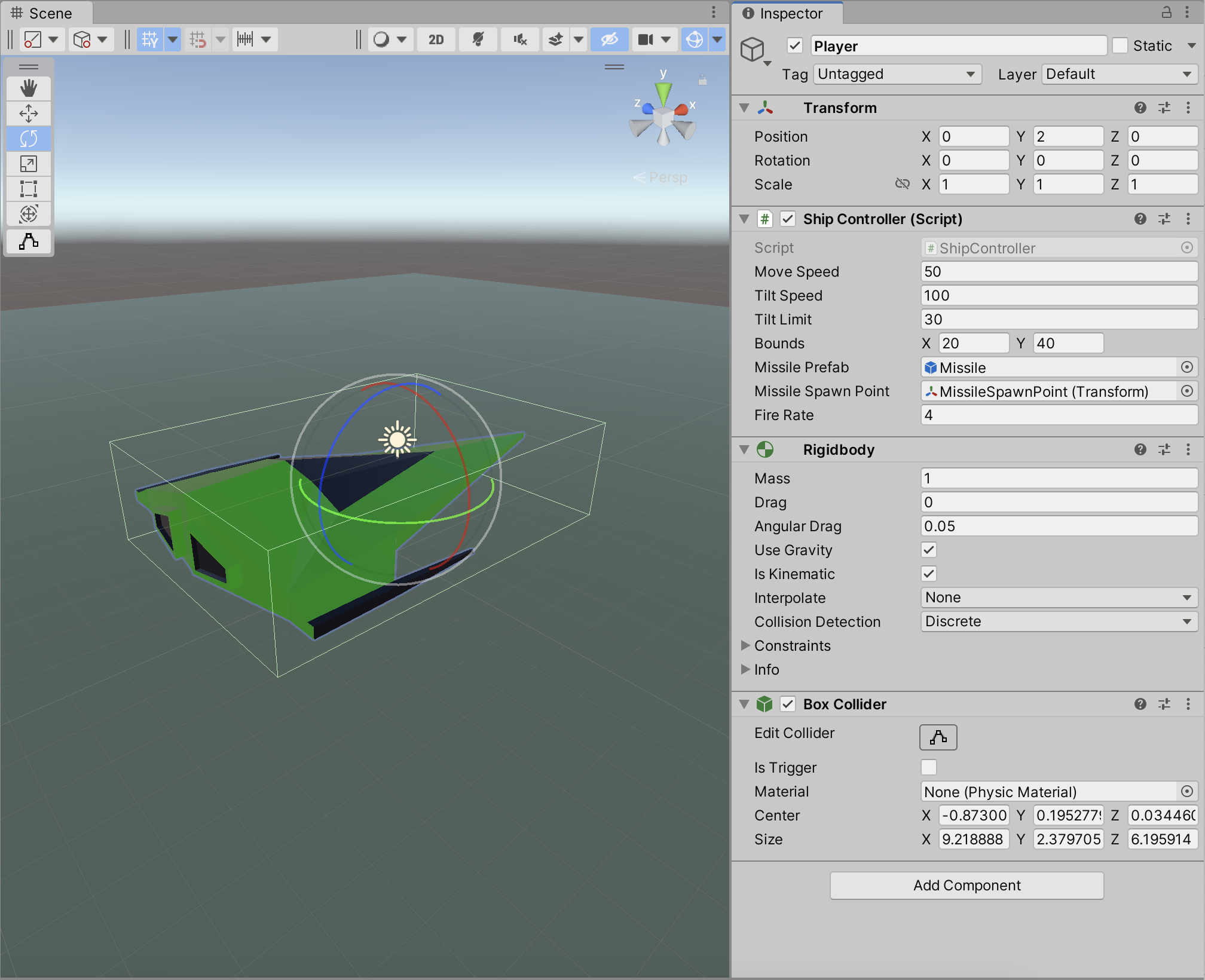
I thought we’d done this ages ago, but we never implemented bounds checking for our ShipController. It’s only supposed to be able to move within a fixed area. To achieve this we added a new property to ShipController of type Vector2d called Bounds. We are going to use the x part of this property to store how far we want to allow the ship to move forward and backwards and we’re going to use the y part to store how much we want to allow the ship to move side-to-side. In testing we found good values for this were (20, 40). Here’s the change to the ShipController.Update() function:
    Vector3 newPos = transform.position +
                         new Vector3(moveInput.y * MoveSpeed * Time.deltaTime,
                                     0,
                                     -moveInput.x * MoveSpeed * Time.deltaTime);
    if (newPos.x > Bounds.x)
      newPos = new Vector3(Bounds.x, newPos.y, newPos.z);

    if (newPos.x < -Bounds.x)
      newPos = new Vector3(-Bounds.x, newPos.y, newPos.z);

    if (newPos.z > Bounds.y)
      newPos = new Vector3(newPos.x, newPos.y, Bounds.y);

    if (newPos.z < -Bounds.y)
      newPos = new Vector3(newPos.x, newPos.y, -Bounds.y);

    transform.position = newPos;
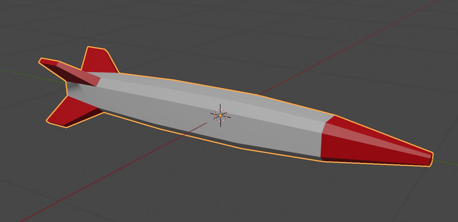
We made a simple missile in Blender and exported it as an FBX file and imported it into Unity. We then created and empty GameObject, placed the missile model under it in the hierarchy and created a prefab from them.
Once in the prefab folder, we edited the prefab and added a ConstantMovement behaviour and a DestroyOnDistance behaviour. This makes the missile fly and eventually destroy itself.

First we had to edit our ShipControlls.inputaction in our Inputs folder by double clicking on it. We then added a new action of type Button called Shoot with a single Binding to the Spacebar on the keyboard.


We used the Save Asset button on the dialog above to save the input actions.
In our code then in ShipController we added the following at the bottom of update:
    // Shooting
    if (_controls.Ship.Shoot.WasPerformedThisFrame())
    {
      Debug.Log("Shoot was pressed on frame " + Time.frameCount.ToString());
    }
This allowed us to see that the shoot command was being picked up with a message getting written to the console every time the spacebar was pressed.
We added two new properties to ShipController:
  public GameObject MissilePrefab;
  public Transform MissileSpawnPoint;
The first is to store our Missile prefab and the second is to store a location under the ship where the missile can be launched from. To create this we added an empty called MissileSpawnPoint under Player in the scene and, in a side view, moved it down below the ship and towards the front of the ship.

We could then assign this and the missile prefab to the appropriate properties of ShipContoller attached to the Player object.
In PlayerController we swapped the call in Update() to Debug.Log() for a call to a new private function Shoot() which we also created, to look like this:
  private void Shoot()
  {
    // Create a missile at the missile spawn point
    Instantiate(MissilePrefab,
                MissileSpawnPoint.position,
                MissileSpawnPoint.rotation);
  }
Every time now that the spacebar is pressed, a missile is created below the spaceship and flies forward for approx. 8 seconds before destroying itself.
It’s unrealistic to be able to shoot missiles as quickly as we can hit the spacebar, so some idea of fire rate is useful. It’s easy to convert a rate into an interval, all you have to do is divide one by the rate to get the interval. For example, if the rate is 2 per second then the minimum interval between shots is 1/2 = 0.5 seconds. Similarly, if the rate is 10 per second then the minimum interval between shots would be 1/10 = 0.1 seconds.
We add a new property to ShipController called FireRate.
public float FireRate = 1.0f;
We also add a couple of private properties:
  private float _minTimeBetweenShots;
  private float _lastShotTime = -10.0f;
The first of these is the minimum interval between shots. We calculate if from the rate, as described above. Since we just need to do this once, we pop the code in Start():
  void Start()
  {
    _minTimeBetweenShots = 1.0f / FireRate;
  }
The second private property stores the last time we fired a missile. We set it to a arbitrary large negative value so that at the start of the game it’s the same as if it’s been ages since we fired a missile, even though we’ve never actually fire one yet.
We can now check the time since we last fired a missile against the minimum time between shots in the Shoot() function:
  private void Shoot()
  {
    if (Time.time - _lastShotTime < _minTimeBetweenShots)
      return;

    // Create a missile at the missile spawn point
    Instantiate(MissilePrefab,
                MissileSpawnPoint.position,
                MissileSpawnPoint.rotation);

    _lastShotTime = Time.time;
  }
All the code we’re made this year is on our GitHub. It can be found here. If you don’t have the latest version of our code before any session, use the green Code button on that page to get the “Download ZIP” option which will give you a full copy of all code we’ll be writing this year.
