Creators Quiz Time

This week at Creators we took some time out to play some games and do some quizzes – well done to everyone that took part!  We used the fantastic website “Kahoot!” to drive the quizzes.  Some of you had used this site before in school.  We had a little trouble getting it going due to network trouble, etc but got it sorted and interestingly saw how we could debug the issues in the kahoot javascript using the console to see that it was the network causing the problems, just like we did with our own code.

Anyhow the results of the quiz are below – everyone did brilliantly as expected but LORD PJO showed her quickfire dominance by amazingly winning two of the three games:

We then did a rapid-fire challenge to do a circle that changes color when the mouse is over it.  This is one of those ones that is easy in scratch (“touching mouse”) but we hadn’t covered collision detection really in javascript so you had to figure it out.  Most all of you got it, some with really clever solutions!  My pretty simplistic solution is checked up to github as usual.

Next week we have a break and then we plan to spend a week working on our own ideas – anything you like – either bring in a project that you are working on and Kieran and I will try to give advice or just start a new one in the class and we’ll try to get you off on a good footing.

A WebGL 3D Solar System!

solarsystem

This week we looked at WebGL and how it can be used in Javascript to easily create 3D animations and games.  After looking at different shapes for a while, someone suggested building a solar system so that’s what we did!  This project just did the first sample planet.

The code is up on github as usual!

Click here to view the project we did on Saturday!

What is WebGL?

WebGL is a javascript API that allows your programs to use the graphic cards on your computer.  Graphics cards are built for really fast graphics and have specially encoded hardware to quickly do the calculations needed for common graphics.  With 2D, you can often get away without graphics cards, but they really make things a lot faster in 3D!

There are several javascript libraries that let you use webGL – the most famous and probably the best of them is one called three.js, which lets you do really advanced 3d – however our trusty p5.js also has a pretty decent set of functions and for us is much easier to use.

Initializing the p5 canvas for 3D

The great thing we found about p5.js 3d is that is is REALLY similar to the 2D shape functions, so much so that we all intuitively were able to get going with little need to look at documentation.

Sadly, it’s not easy to mix 2D and 3D code in P5 as the “canvas” is created differently.

To get it started, we had to add one word to the createCanvas function call – “WEBGL” – so to create a canvas we use the function:


setup() {

createCanvas(800, 600, WEBGL);

}

P5 3D primitives

There are many better reference guides online so I won’t go int great detail here but the main built-in shapes that you can use to create things with are:

  • Box for all manners of cuboids
  • Plane for a flat plane (a “rect” also works actually!)
  • Sphere for a (duh!) sphere
  • Ellipsoid for a rugby ball shaped thing
  • Cone for a cone-shape
  • Torus for a donut shape
  • Cylinder for a cylinder

Using these basic building blocks, it’s possible to create all manner of shapes.

There is also a “loadModel” function that allows you to read in a model from a 3D package like “Blender”.  These can be models of spaceships, bad-guys, houses, ponies, whatever you like!  Maybe at some stage in the future we’ll try to learn a bit about blender.  One of the ninjas already had played with blended and managed to load in a model of a meteorite he’d been working on!

Positioning shapes

The models and shapes don’t have any coordinates on them – it’s all stuff like size and grid size.

Our first program involved creating a box and moving it around.

To position the shapes you use the “translate” function, just like you can in 2d. With this we moved the shape around


function draw(){
background(50);

push();
translate(0, 0, 0);
box(100, 100, 100);
pop();

// increase X - move right
push();
translate(200, 0, 0);
box(100, 100, 100);
pop();

// increase Y - move down
push();
translate(0, 200, 0);
box(100, 100, 100);
pop();

// upper left and closer to viewer
push();
translate(-200, -200, 200);
box(100, 100, 100);
pop();
}

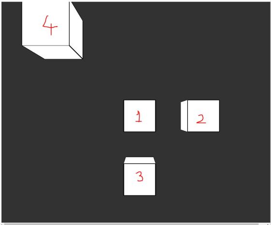
We quickly noticed that the axis are slightly different:

  1. The box appeared in the center of the screen – i.e. 0,0 is the middle of the screen (like scratch) rather than the top left. (Box 1 below)
  2. Making X bigger moved it to the right (Box 2)
  3. That making Y bigger still moved it “down” unlike scratch! (Box 3)
  4. That making Z bigger moved it towards the viewer (Box 4)
  5. That there is perspective automatically built in

cubeFade

To Rotate shapes, there are three functions that are handy: rotateX, rotateY, rotateZ – these can rotate around the axes.  Just like in 2D the ddefault unit is radians so you need to set angleMode(DEGREES) if you want degrees.  For example – rotating the box by 45 degrees is per below:

angleMode(DEGREES);
rotateX(45);
box(50, 50, 50);

Push() and pop() can be used to stack the transformations on top of each other – just like in the 2d sketches!

Lights!

We learnt that there are three types of light:

  1. AmbientLight is light which comes from everywhere – it casts no shadow.  We just give it a color ambientLight(255) is a white ambient light for example
  2. pointLight is a light which is centered on a point.  It just has a color and a position – e.g. pointLight(r, g, b, x, y, z).  Pointlights are pretty dim, but you can stack lots of them on the same location to make them brighter – this is what we did for our sun!
  3. directionalLight is a light which has a color and a direction – this is very similar to the pointLight except that the light just shines in one direction and can be used for e.g. spotlights.

Material!

Depending on the material, the light reflects different ways – the main material types we tried were:

  • ambientMaterial: This is normal “Matte” material
  • specularMaterial: this is reflective material – it shines back like glass or water
  • normalMaterial: This is the default material type – this is kind of weird looking to me and I’d usually use ambient…

For each of these types, you simply set the material before drawing the shape – kind of like the fill function.

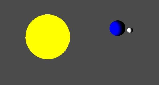
Explaining the Solar System Code

Our “Solar System” code was very basic – what we have here was one planet orbiting around a Sun in a spherical orbit, with a moon orbiting around that planet.  We didn’t have any physics in there – just spheres orbiting each other.

We did the following:

  1. set nostroke
  2. started a rotation around the Y axis
  3. created a bunch of lights at the center where the sun is
  4. drew a big yellow sphere for the sun
  5. translate 300 pixels out to draw a blue sphere
  6. set it’s rotation to 12 times faster than the “earths”
  7. moved 50 pixels out.
  8. drew another small white sphere

This sounds like a lot but the code is really simple and can be seen here.

Challenge!!

We did one planet and moon in the class because a lot of the time was spent playing with our own projects.  How about you take our solar system and change it so that all the planets have accurate relative rotation speeds?  i.e.

Mercury: 87.97 days (0.2 years)
Venus : 224.70 days (0.6 years)
Earth: 365.26 days(1 year)
Mars: 686.98 days(1.9 years)
Jupiter: 4,332.82 days (11.9 years)
Saturn: 10,755.70 days (29.5 years)
Uranus: 30,687.15 days (84 years)
Neptune: 60,190.03 days (164.8 years)

Try putting a ring (torus?) around Saturn!

The distance from the sun could also be put in, but it might be a bit weird looking – in fact you wouldn’t even see most of the planets as they get pretty spaced out as you move out!

Week 9 Explorers – Scrolling backgrounds

Hi Everyone

We started work on on our scrolling platform game this week and I showed you all how to get started. You can customise even further to suit your game as the weeks go on .

To understand the concept, you must understand that the STAGE is only 480 pixels wide (x goes from -240 to +240). No one SPRITE can be larger than the STAGE and we won’t be able to see a SPRITE that isn’t on the STAGE (ie. it’s x position is less than -240 or greater than +240). So we have to set up a series of SPRITES that extend past the stage and move them across the stage from left to right and under Mario’s feet to make it look like he is moving over the ground from right to left!

1. We started picking our character from the internet or from the Sprite Library

2. Next, we drew our own Ground SPRITE using the PAINT NEW SPRITE button. Important!! The sprite must be the full length of the stage!! See the 1st picture above for an example of what the ground sprite could look like. Mine looked like a brick wall, but yours can look like a stone wall or concrete one or some kind of footpath or road.

3. Now we must code our Ground SPRITE! We need to set it’s inital x position to zero and continuously move it in a direction for as long as we are pushing the right or left arrow buttons. To do this we need a new VARIABLE called XPOS. Go to DATA and create this new VARIABLE. See the image below on the bottom the instructions for setting up the initial position of the first ground SPRITE. After you create and code the first one, we can duplicate Ground SPRITE 1 and create Ground SPRITE 2. Be sure that Ground SPRITE 2 has an xpos set to 480 pixels more than Ground SPRITE 1.

cda-s5-challenge-12-scrolling-ground_sprites_1

4. Lastly, for this week, we need to get the Ground SPRITES to move!!

!!IMPORTANT! !Click the little i button on your Ground  SPRITE and see all the information about the SPRITE. Change the rotational direction of the Ground SPRITE to non-rotational. It is a button that looks like a dot.

We then coded the Ground SPRITES to move to the left when we press the left arrow key and to the right when we press the right arrow key on our keyboards.  See below: Be careful to program the left arrow key to Point In Direction 90 and the right arrow key to Point In Direction -90. Notice both the Change xpos By commands have different numbers! (-5 and +5) Get these wrong and the SPRITE will not move in the correct direction. Once you have the 1st ground SPRITE working the way you like, duplicate it and all it’s coding. All you have to change in Ground SPRITE 2 is the xpos. It must be set to XPOS +480. If you duplicate that sprite, you must set it’s xpos to XPOS + 960 and so on and so on…cda-s5-challenge-12-scrolling-ground_sprites_2

We will add some obstacles this week and maybe have some rewards for our character as well.

See you Saturday


Martha

Bodgers – Pygame Zero

This week we took a break from hardware and we looked at Pygame Zero. Pygame Zero is for creating games quickly and with fewer lines of code than would be used with Pygame. It is intended for use in education, so we can learn basic programming without needing to understand the Pygame API or how to write an event loop.

Pygame Zero is designed for the Raspberry Pi but it can be installed on other systems, we used Windows without much hassle. It comes installed on the Raspberry Pi already if you have a recent version of Raspian. To install on windows open a command prompt and type:

pip install pgzero

You may need to install Pip if you didn’t install it when you installed Python. To do this go to Control Panel/Settings and then Add/Remove Programs, scroll down and click on Python then click on modify, tick the Pip check box and save your changes.

To run your code from Idle or any other IDE you need to add two lines to your code, at the beginning before any other code you need:

import pgzrun

and at the  end of your code put:

pgzrun.go()

We will be using Pygame Zero for graphical input/output in our projects but if you want to have a go at writing a game, CodeConjuring’s Froggit youtube tutorials are a good place to start.


See you all next week.

Declan, Dave and Alaidh.

Fractal Fun In Javascript

This week in Creators we looked at a brand new concept – functions that actually call themselves – also known as recursion.

recursion1

Though this seems at first glance like a really silly thing to do, we were quickly able to use it to generate some pretty effects.

The main things to remember about the recursion are:

1. Make sure to give it something that will let it exit – a function calling itself forever will not work and the browser will crash or throw an error.  For us, we passed a value as a parameter and made it smaller each time, exiting when it fell below a certain value.

2. Do the math! Recursion leads to big numbers of operations very quickly and can slow down or crash a browser easily.  Make sure to save often and think about the amount of times your function will run.

Recursion is really handy for cases where there are lots of operations that are similar.

Circle Pattern Project

In this project, we wrote a function which draws a shape (we picked a circle) before calling itself three times to draw the shape to the left, right and below.  The code is below:


function drawShape(x, y, size){
if(size > 5){
stroke(random(255), random(255), random(255));
fill(size, 50);
ellipse(x, y, size, size);
drawShape(x+size/2, y, size/2);
drawShape(x-size/2, y, size/2);
drawShape(x, y+size/2, size/2);
}
}

Notice the If statement?  This means that it will not bother drawing circles smaller than 5 pixels in diameter – this allows the code to work.

This simple code generated the following pretty fractal:

fractal_circles

Fractal Tree

For the next project, we used very similar code to create a beautiful fractal tree.  In this case we wrote a “drawBranch” function which can draw a branch at a given angle and length.

We added a little code to allow us to change the angle that the branches fan at – the fanangle – dynamically.  Depending on the variables, we could slow down our computer quite easily – the trick is to think about how many lines your computer will need to draw.

recursive-tree-steps

Each function called itself to draw a pair of smaller branches off of it.  The tree is shown below – just before I checked the code in, I added a little if statement to color the branched brown if the length is > 50.  The result is below:

fractal_tree

This looks quite pretty and is fun to play with if you have a pretty fast computer – play with it here:

https://coderdojoathenry.github.io/creators2017/week16-tree/index.html

As usual, all of our code is on the Creators 2017 github repository.

Creators: Robot Arm

cpccg_screening_robot

This week we looked at a representation of a robot arm. The body of our robot is allowed to slide horizontally and the arm can pivot at the shoulder (where the upper arm attaches to the body) and at the elbow (where the lower arm attaches to the upper arm).

Transformations

An important point about this project was to show how transformations add up together. Transformations include translations (moving in straight line), rotations (turning about a pivot point) and scaling (changing size). We’ve used translations and rotations for our robot.

In P5, the origin, or place where the x and y coordinates are both zero is at the upper left-hand corner of the screen. The x coordinate gets bigger as we move right and the y coordinate gets bigger as we move down.

When we translate, we move the origin to somewhere else. This is handy for a few reasons but if we are performing rotations. All rotations happen around the origin, wherever that happens to be at the time.

This diagram shows all the transformations we use for our robot:

Robot DOFs (1)

  1. Translate to move the origin to the centre of the robot body
  2. Translate to move the origin to the shoulder
  3. Upper arm rotation at the shoulder
  4. Translate to move the origin to the elbow
  5. Lower arm rotation at the elbow

Because these transformations stack up on top of each other, this is what each part experiences:

  1. Body – Transformations: 1
  2. Upper Arm – Transformations: 1, 2, 3
  3. Lower Arm – Transformations: 1, 2, 3, 4, 5

The body is only affected by one, but the lower arm is affected by all five.

Movement

To move the robot, we set up three variables:

  1. bodyPos to store the body position (our first transformation)
  2. upperArmAngle to store the rotation at the shoulder (our third transformation)
  3. lowerArmAngle to store the rotation at the elbow (our fifth transformation)

We created a function called handleInput() called from the draw() function (which is called every frame). In that we used the keyIsDown() function from P5 to check for keys being held down. We made the left/right arrow keys move the body horizontally, the up/down arrow keys rotate at the shoulder and the Z/X keys to rotate at the elbow.

Source Code

As always, the code can be downloaded from our GitHub repository.