We completed our dioramas with materials and lights and rendered the final images. Some people chose their own colours and some used a palette generator (see: https://coolors.co/bf4e30-c6ccb2-093824-e5eafa-78fecf) to choose a complimentary set of colours to provide a harmonious look for our scene.
We used the Cycles rendered and turned on the denoising options, which automatically remove any graininess from the resulting render, to give us a high-quality output in a reasonable timeframe.
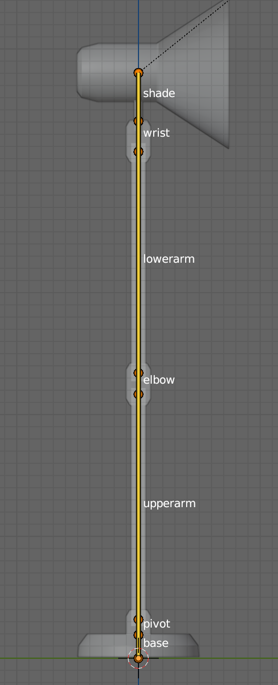
We then built a simple model of an articulated desk lamp. Built as a single mesh and composed of simple primitive objects, all starting as cylinders or cubes, we developed it initially in a completely linear vertical configuration.
We then created vertex groups for each distinct portion of the lamp and assigned those parts of the lamp to those vertex groups. From the bottom up, these groups were:
base
pivot
upperarm
elbow
lowerarm
wrist
shade
We then added a spot light to represent the lamp’s bulb.
Next we generated a new armature. In edit mode, we scaled the initial bone until it was just the size of the base vertically and called it base, the name matching that of the vertex group in the lamp model. We then extruded the tip of this bone vertically to the centre of the first hinge pin in the model. This bone was named pivot again matching the name of the corresponding vertex group. We repeated this until there was a bone, named for the corresponding vertex group, across each section of the model.
We then returned to edit mode and, selecting first the armature and then shift-selecting the model, we used Parent | Armature Deform from the object menu to associated them together. The mesh became a child of the armature. Selecting the armature and changing to Pose mode, we were able to see how rotating the bones allowed us to move the model in a simple and non-destructive way.
We then wanted to move the light with the armature as well, as it currently remained in space where we’d located it originally. To do this we selected the spotlight object and added an object constraint tying it to the the shade bone in the armature, as shown below. This moved the light, so we needed to reposition and rotate it again to get it in the correct location.
The final step was adding an inverse kinematic control bone into the rig. Moving an inverse kinematic (IK) bone automatically moves all connected bones to try to follow the movement of the control bone. In the armature, in edit mode, we added a single bone and located it near the rim of the lamp shade. We called it “control” and, selecting it and then the shade bone, used Armature | Parent | Make | Keep Offset to join them.
We then switched to pose mode. Once in pose mode, we could add an IK constraint to the control bone as shown below. All defaults here are fine in this case.
Then we saw that moving this bone in Pose mode caused the rest of the lamp to follow, however some parts of the lamp were moving in ways we didn’t want. The final step was to place some IK limits on certain bones in the Bone Properties Panel. For the base we locked x, y and z because we didn’t want it to rotate at all:
For pivot and shade, we locked then in x and z, this will allow them to turn around their own axis but not bend over. For all the others we locked them in y and z allowing them to bend over corresponding to the way they were pinned in the model.
Files for these final models can be found on our Sharepoint site.
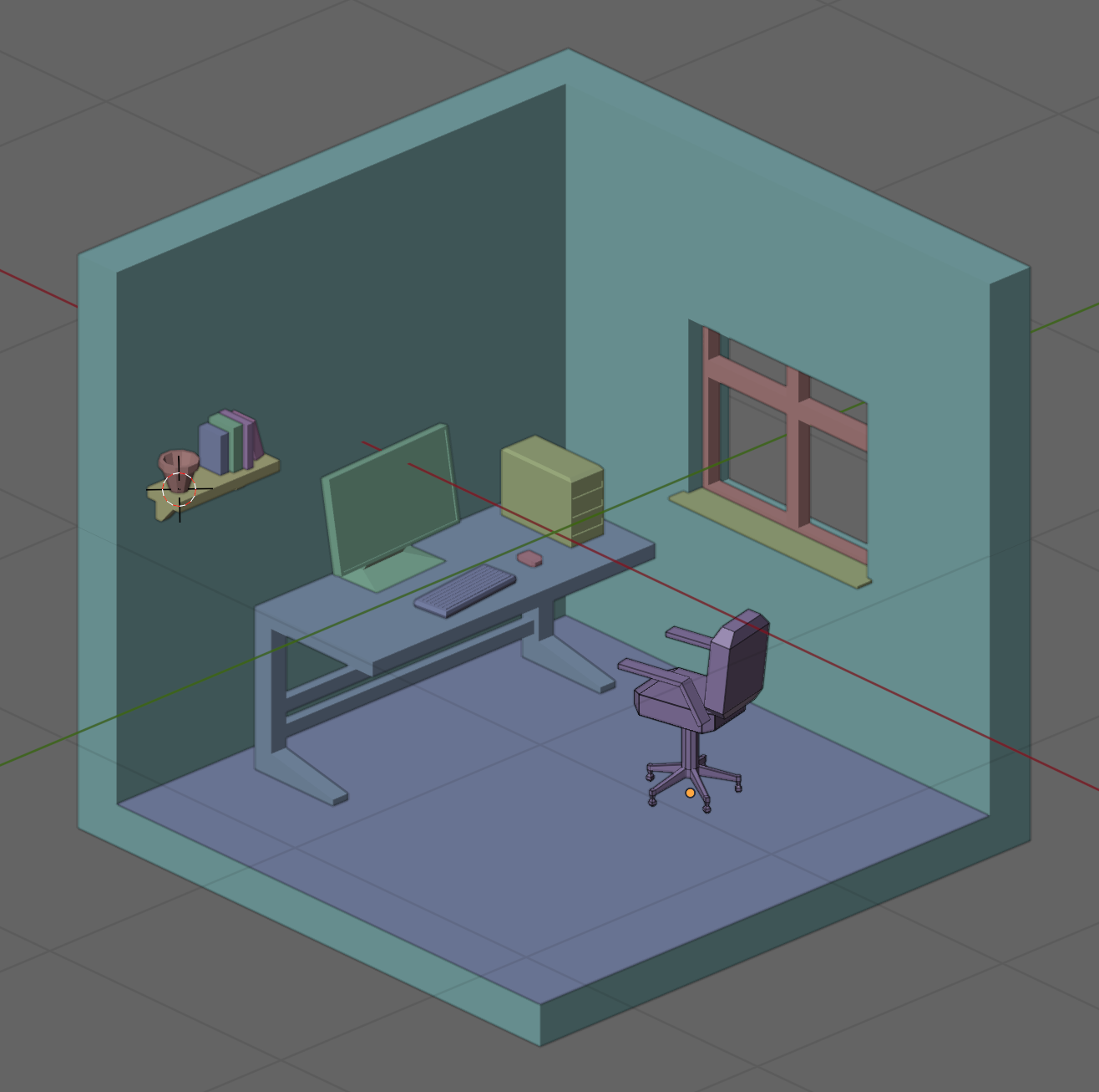
This week we continued with adding more props to our diorama. Of these the gaming chair was the most complex.
To make the five-footed design of chair base we started with a cylinder with twice as many sides and then, after placing an edge loop near the bottom, extruded every second face to form the feet. We then extruded these feet ends a second time and extruded a few more times to form a roughly spherical shape to represent coasters.
The chair seat was just a cube, scaled to the appropriate proportions and then the front and back faces extruded and scaled slightly to round out the shape. We duplicated the seat and moved and rotated it to form the chair back as well.
The arms were created by first duplicating the faces on the left and right of the chair seat, scaling them vertically and moving them up into position. The reason for doing this with copied faces was because it ensured they were perfectly aligned to the rest of the chair. These faces where then extruded with the “Extrude along face normals” command [Keystroke: Alt-E] to give them width. Finally we extruded the back faces of these two arms, down to the bottom of the chair back, by selecting them, going to a side view and using the Ctrl-Right Click command.
We also added a few more simple props. These were all based on cubes, scaled to size and shaped using inset, extrude and edge loops.
This is the final room, from a geometry perspective. We still need to give materials to the objects, light the scene and render a final image.
Files for this weeks work-in-progress model can be found on our Sharepoint site.
After mostly doing a review of the basic functions of Blender in Weeks 1 and 2, we started our first real project this week; a diorama of a room populated with low-poly props, rended by an orthographic camera from an isometric perspective.
Most of the time we use perspective cameras. With perspective cameras, like in the real world, things appear smaller the further away they are. An orthographic camera does not have that effect; things stay the same size no matter how far away they are. In the image above the right-hand pane shows the view from the orthographic camera while the left-land shows a standard perspective view. You can see how the cube shape is emphasised using the orthographic camera; it’s a stylistic choice.
We are also using an isometric view point. This is one where the camera is positioned approximately the same distance along each axis and looking back towards the origin. It’s a style of presentation that has been made popular in many games down the ages and again is a stylistic choice. Search Google Images for “game isometric” to see examples.
We learned how to split the Blender view by dragging from the bottom left corner with the mouse. This split view allows us to maintain the camera view on one screen while we actively edit on the other.
We set some options for Viewport Shading to help understand the model as we build it. These are shown above. Shadow and cavity help emphasise edges and geometry. Switching “Color” to “Random” helps us quickly visually distinguish distinct object while we still don’t have separate materials assigned to them.
All the objects were built with the following techniques:
Loop-cuts
Edge and face loop selection, movement and scaling
Inset
Face duplication and separation (to create new objects)
Bridge edge-loops
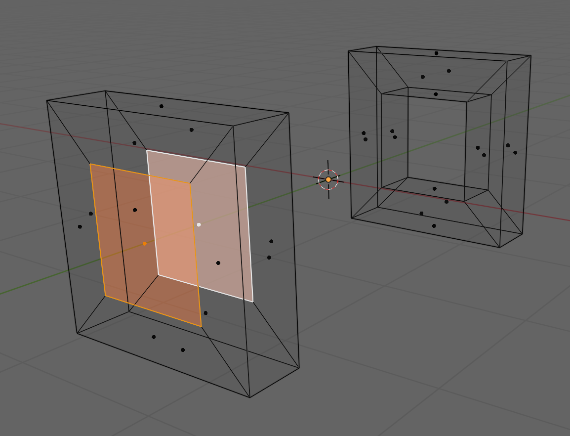
The first three of these are very familiar, but we can talk about the other two. A few places, such as around the hole in the wall cut for the window, we had a set of existing faces that could be repurposed to form the basis of another object, in that case the window itself. Duplication of faces is accomplished with the keystroke shift-d, followed by enter to confirm. The duplicates, already selected, can then be separated by pressing p and choosing “Selection”.
Bridging edge loops we used in two ways. In the first, we had faces on opposite sides of a box. Selecting them both and choosing “Bridge Edge Loops” from the “Edge” menu causes a hole to be punched out between these faces,. The original faces are removed and the internal edges of the new hole are filled in.
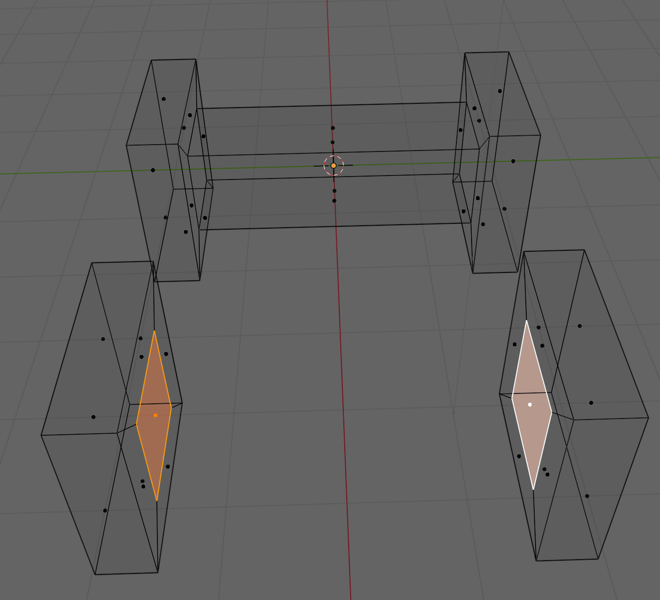
The second way we used it was to join two faces opposing each other across a gap. In this case the faces are again themselves removed and a solid connection between the faces original locations is created across the gap.
Next we are going to continue to model props within the room and, time permitting, assign materials and render a final image.
Files for this weeks work-in-progress model can be found on our Sharepoint site.