Bodgers – Cool Projects

Hello again everyone.

In the Bodgers group we’re starting to put our projects together for the Coolest Projects Showcase.

“Coolest Projects International is a world-leading showcase for young innovators who make stuff with technology. If you’re up to 18 and you’re making something with technology for fun, to solve a problem, or as a creative outlet, then we want you to come out and share your project with us! This free event will take place in the RDS Main Hall, Dublin, Ireland on 5 May 2019.”

Find out more here: https://coolestprojects.org/

If you have any questions you can contact me at coderdojoathenry@gmail.com.

Don’t forget we’re off for the next 2 weeks, we’re back on 27-Apr-19.

see you all then.

Declan, Dave and Alaidh

Bodgers – RFM69 Radio Modules


DSC00227

Hello again everyone.

This week we looked at the Adafruit RFM69HCW Radio Module, these modules allow us to send messages between Arduinos without using Wifi or Bluetooth.

Adafruit have a tutorial here on setting up the module. The basic steps are:

  1. Solder on the header pins.
  2. Solder antenna or wire cut to the the proper length for the module/frequency
    • as our frequency is 433 MHz  we cut the wire to 16.5 cm.
  3. Wire up modules to your Arduinos
  4. Download the RadioHead library to your Arduino IDE.
  5. Load the RadioHead69_RawDemo_TX code from this library to the Arduino you’re using to transmit.
  6. Load the RadioHead69_RawDemo_RX code from this library to the Arduino you’re using to receive.
  7. Test

Next Saturday we will be putting all of the different components from our projects together and testing out how they work.

see you all then.

Declan, Dave and Alaidh

Bodgers – GPS


This week we looked at GPS which stands for Global Positioning System. The idea behind GPS is based on time and the position of  a network of  satellites. The satellites have very accurate clocks and the satellite locations are known with great precision.

Each GPS satellite continuously transmits a radio signal containing the current time and data about its position. The time delay between when the satellite transmits a signal and the receiver receives it is proportional to the distance from the satellite to the receiver. A GPS receiver monitors multiple satellites and uses their locations and the time it takes for the signals to reach it to determine its location . At a minimum, four satellites must be in view of the receiver for it to get a location fix.

We used the Adafruit Ultimate GPS Breakout connected to an Arduino as our GPS receiver. It’s very easy to set up, all we did was install the Adafruit GPS library on our Arduino and this gave us a load of programmes to chose from. We used the parsing sketch which gave us Longitude, Latitude and our location in degrees which we used with google maps to show our location.

See you all again on the 23/Mar/19

Declan, Dave and Alaidh


Bodgers – Introduction to Arduino

Hello again everyone.

I was away this week so Dave led the group, they did a couple of Arduino projects. They  revisited the traffic lights from December but this time used the Arduino to control them and then moved on to  a temperature and humidity sensor called the DHT11.


Here is the wiring diagram for  the traffic lights and you can find the code here.

arduino lights


Here is the wiring diagram for the DHT11 and the code is also on Dropbox here.

dht

We will be doing more with the Arduino particularly for some of our projects.

See you All again on Saturday

Declan, Dave and Alaidh

Hackers – Controlling Robot Wheels and Handling Interrupts in Arduino

IMG_20190202_135834

Controlling Robot Wheels

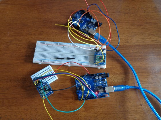
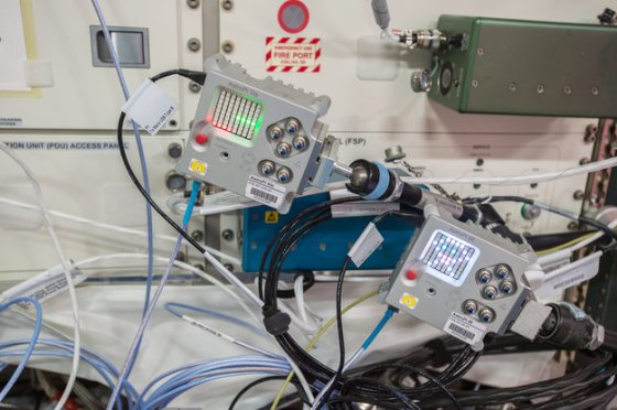
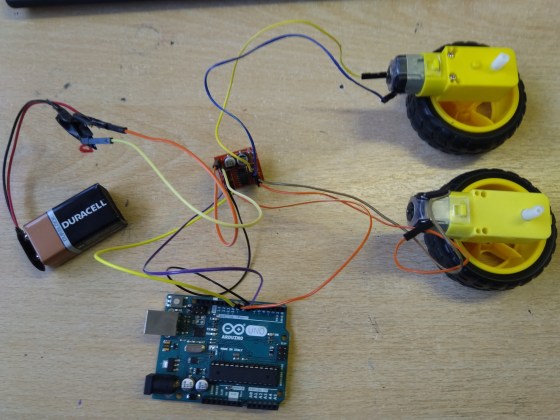
Last week, we figured out how to control a motor with a H-bridge. We expanded this to controlling a pair of wheels using the H-bridge. Above is a photo of the hardware. The wiring of the H-bridge is:

  • H-bridge [+] and [-] are connected to a 9V battery
  • H-bridge [IN1] to [IN4] is connected to Arduino Pins 6, 7, 8, 9
  • H-bridge [Motor A] and [Motor B] pins are connected directly to the two motors

Below is Arduino code by Hackers member Luke to control this.

// Luke Madden, CoderDojo Athenry
// Control motors using a H Bridge

// The H bridge has 4 input pins: in1-in4
#define in1 6
#define in2 7
#define in3 8
#define in4 9

int fast = 150;// range 1-255
int slow = 80;// slower speed
int hyperspeed = 255;// hits the hyperdrive

void setup() {
  pinMode(in1, OUTPUT);
  pinMode(in2, OUTPUT);
  pinMode(in3, OUTPUT);
  pinMode(in4, OUTPUT);
  Serial.begin(9600);
}

void loop() {
  drive();
}

 void drive() {
  // Test the functions
  Serial.println("move forward");
  forward();
  delay(2000);

  Serial.println("hit the hyperdrive");
  hyperdrive();
  delay(2000);

  Serial.println("go backwards");
  backwards();
  delay(2000);
}

void forward() {
  //makes motor go forwards
  analogWrite(in1, fast);
  analogWrite(in2, 0);
  analogWrite(in3, fast);
  analogWrite(in4, 0);
}

void hyperdrive() {
  //hits the hyperdrive
  analogWrite(in1, hyperspeed);
  analogWrite(in2, 0);
  analogWrite(in3, hyperspeed);
  analogWrite(in4, 0);
}

void backwards() {
  //makes motor go backwards
  analogWrite(in1, 0);
  analogWrite(in2, fast);
  analogWrite(in3, 0);
  analogWrite(in4, fast);
}

void stopping(){
  //makes it stop
  analogWrite(in1, 0);
  analogWrite(in2, 0);
  analogWrite(in3, 0);
  analogWrite(in4, 0);
}

Handling Interrupts in Arduino

In Arduino, you can set up special functions that are a called depending on the state of some digital pins – these are called Interrupt Service Routines (ISRs). These routines are called separately from the main loop() that is always running, even if the main loop() is in the middle of another operation.

For controlling our robots, our Arduino might receive a signal on a pin, and if we want the robot to react quickly, an ISR can handle it. The ISR can send a signal on a different pin or change the state of a variable.

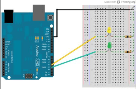
This code is simple and correctly-working demonstration of how interrupts work. Note that you don’t need to build any circuitry to try this out. A built-in LED on the Arduino, at pin 13, turns on/off depending on whether Pin 2 is connected/disconnected from the the GROUND pin.

There are three main tasks:

  1. Define the ISR function: this is a function declared as void with no arguments: for example, our ISR is called changed and is defined as:
    void changed() { … }
    In our code, it sets the value of a variable called controlState and it turns the LED on/off. Note that the value of controlState is printed out repeatedly in the main program loop, showing how the ISR can change a variable that is used elsewhere.
  2. In the setup() function, set the pin mode of the control pin to INPUT or INPUT_PULLUP (see below for the difference). For example, we have defined the variable control to have value 2 and are setting its mode like this:
    pinMode(controlPin, INPUT_PULLUP);
  3. In setup(), attach the ISR to the pin:
    attachInterrupt(digitalPinToInterrupt(controlPin), changed, CHANGE);

One extra note about the above line of code: all pins have numbers and all interrupts have numbers, and these are not (necessarily) the same numbers. The function digitalPinToInterrupt() returns the interrupt number corresponding to a given digital pin.

Some other things to note:

  • The Interrupt Service Routine (ISR) should be short and run fast: delay() calls are ignored and print() can cause problems.
  • You can’t attach two interrupts to the one pin: use CHANGE and then test pin state
  • If you initiate the pin with INPUT_PULLUP, it is triggered by connecting it to GROUND; otherwise, if you initiate it with INPUT, you need a circuit with 10k resistor.
  • On an Uno, can only attach interrupts to pins 2 and 3.
  • If you are changing a variable in the ISR and need to use it elsewhere, declare it as volatile.

Here is the full Arduino code:

// Michael Madden, CoderDojo Athenry
//
// Test a pin interrupt to which an interrupt service routine (ISR) is attached.
// When the control pin is connected to GROUND, the LED on the board is turned on.

// Things we have figured out:
// * The interrupt service routine (ISR) is a function declared as void with no arguments.
// * It should be short and run fast: delay() calls are ignored and print() can cause problems.
// * You can't attach two interrupts to the one pin: use CHANGE and then test pin state
// * If you initiate the pin with INPUT_PULLUP, it is triggered by connecting it to GROUND;
// * otherwise, with INPUT, you need a circuit with 10k resistor.
// * On an Uno, can only attach interrupts to pins 2 and 3.
// * If you are changing a variable in the ISR and need to use it elsewhere, declare it as volitile.  

const byte controlPin = 2; // Want to react when this pin is triggered
const byte ledPin = 13; // no circuit needed: there is a built in LED on 13
volatile int controlState = 0; // will change this value in ISR

void setup() {
  pinMode(ledPin, OUTPUT);
  pinMode(controlPin, INPUT_PULLUP);
  attachInterrupt(digitalPinToInterrupt(controlPin), changed, CHANGE);

  Serial.begin(9600);
}

void loop() {
  // The main loop does not do much, it just prints out the value of the
  // control pin's state every 2 seconds.
  Serial.print("Current value of control pin = ");
  Serial.println(controlState);
  delay(2000);
}

void changed()
{
  // This is our interrupt service routine.
  // It is triggered when the control pin changes,
  // so we check its state and turn on/off the LED.
  //
  controlState = digitalRead(controlPin);
  if(controlState > 0) {
    digitalWrite(ledPin, HIGH);
  }
  else {
    digitalWrite(ledPin, LOW);
  }
}

Bodgers – Making a start

making

This week we got things off to a flying start with Bodgers Bingo where the Bodgers had to look out for various phrases as I went through a very long slideshow that introduced them to what we do in the Bodgers group, it went very well with lots of Starburst and Chewits for everyone. My slides are here Day 1 (PDF).

We are going to start of the year by working on the Astro Pi Mission Zero Challenge in which the Bodgers will use a Raspberry Pi Sense Hat to write a greeting and display the temperature inside the International Space Station to the astronauts on the ISS. Here are the guidelines for Mission Zero Astro_Pi_Mission_Zero_Guidelines_2018_19 (PDF).

If you’re interested in buying a Raspberry Pi I’d recommend the following sites:

https://thepihut.com/

https://shop.pimoroni.com/

For electronics components and for breadboards etc. I’ve found https://www.bitsbox.co.uk/ are good value, they also do cheap Arduino clones.

That’s all for this week, we’re really looking forward to next week.

Declan, Dave & Alaidh

Bodgers – New Kit & New Projects

Hello again Everyone.

Last week in the Bodgers group we began by looking at our new keyboards and Touchscreens. These will allow us to easily design touch based projects and projects that need a monitor. They will also be invaluable at the start of next years sessions as we can get our code on the Raspberry Pi straight away without any need to connect our laptops.

IMG_20180203_140614

We also started planning our next project with a short brainstorming session and we have a couple of ideas we will develop further this week.


See you on Saturday.

Declan, Dave and Alaidh

Bodgers – Basic Electronics

Hello again Everyone.

I was away this weekend so Dave looked after the group.

He covered some basic electronics theory such as Ohms Law, how we use resistors in our circuits to protect other components and how to wire up an LED. He also helped the group build a simple traffic light circuit controlled by an Arduino which they then programmed.

The Raspberry Pi Foundation have announced that they are not running the Pioneers Challenge this year and are instead concentrating on the Coolest Projects. This means that Coolest Projects is now open to Code Club and Raspberry Jam members. There will be a UK Coolest Projects in April in London and Coolest Projects in Dublin will now be called Coolest Projects International. See more info here.

We have two sessions before the mid-term break so we will concentrate on coming up with ideas for our next projects and how we might implement these ideas and that will leave us a couple of weeks to get components etc. organized.

See you all next week.

Declan, Dave and Alaidh.


Bodgers – Prizes and Plans

It was great to see everybody back after the break.

I had a big box of goodies from the recent Raspberry Pi Pioneers competition. We got more swag for both teams that entered including some very nice badges and three really interesting books.

Our Zombie Trolls also got their prize for failing really well 😊. This included a Raspberry Pi, a 5” HDMI Monitor, some basic electronic components, t-shirts and an Astro Pi Sense Hat (Hat stands for ‘Hardware Attached on Top’).

The Sense HAT add-on board was specially created for the Astro Pi competition which gives kids the chance to get their code running on one of two Raspberry Pi devices that are on the International Space Station.Astro_Pi_Ed_and_Izzy_on_the_ISS

The board gives Astro Pi the ability to ‘sense’ and make many kinds of measurements, from temperature to movement, and to output information using a special display – the 8×8 LED matrix. We had great fun playing around with the Sense Hat and it’s definitely something we will get great use out of and maybe we could enter the Astro Pi competition and have our code running on the ISS.

We also took a look at controlling an Arduino from Unity 3D which is something that could be used for 4D/Immersive Technology type game.

See you all next week.

Declan, Dave and Alaidh


Bodgers – Making More Progress

This weekend in the Bodgers Group our three Raspberry Pi Pioneers teams continued to work on their projects.

The Zombie Herders were working on a PIR (passive Infra-red) sensor which is the type of sensor commonly found in burglar alarms.

IMG_20171022_141129

They used the GPIOZero library for Python and sample code which can be found here. However they didn’t have much success so we need to do more testing on our sensor and if necessary order a new one.

The zombie trolls worked on creating a 3-D model for their project using FreeCAD which they will print out when we return after the break.

stopper_3d

I’m afraid I not allowed to discuss what it will be used for at this point :-).

Team Green Fingers worked on more scripts for their project including using their Arduino and a relay to switch a 12 volt automobile bulb on and off.

flash

As with most projects like this we had a little trouble getting it going as we forgot to set the pin we used on the Arduino as an Output. Thanks to James and his Dad for bringing in the 12 volt powerpack.

We are off for the next two Saturdays and we’re back again on the 11th of November.

See you all then

Declan, Dave and Alaidh.