At our most recent session in the Hackers group in CoderDojo Athenry, we spent out time on practical mathematics, figuring out how, if we want to make a robot that is controlled by a person with a joystick, how exactly do we translate movements of the joystick to signals sent to the motors.
Our assumptions are:
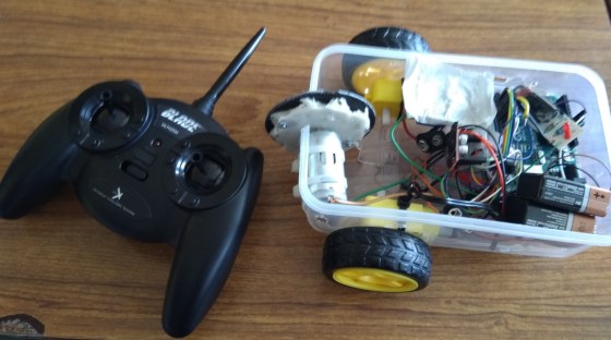
- We are controlling robot with 2 drive wheels, one on the left and one on the right, like the one shown in the photo above (which we made last year)
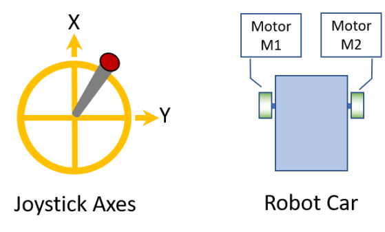
- We assume that we have code to control the motors for the two wheels (which we call Motor M1 and Motor M2) with a value in the range -1 to 1, where 1 is full speed ahead, 0 is no movement, and -1 is full speed reverse
- To make the robot turn, drive the motors M1 and M2 at different speeds
- We assume that we have code to receive signals from the joystick, and get X and Y values in the range -1 to 1, as shown in the diagram below
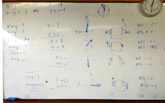
Our approach was to think about what joystick positions (X and Y) should result in what robot movements (M1 and M2), and then see if we could come up a way of expressing M1 and M2 in terms of X and Y. We filled a whiteboard with satisfying diagrams and calculations; see the bottom of this post. I have re-dawn them for clarity below.
The resulting equations are quite simple:
M1 = X + Y, constrained to being between -1 and +1
M2 = X – Y, constrained to being between -1 and +1
Here:
- M1 is the control signal for Motor M1, in the range -1 (full reverse) to +1 (full forward)
- M2 is the same for Motor M2
- X is the forward position of the joystick from -1 (full back) to +1 (full forward)
- Y is the left/right position of the joystick from -1 (full left) to +1 (full right)
- Constrained means: if the calculated value is less than -1, set it to -1; if it is greater than +1, set it to +1.
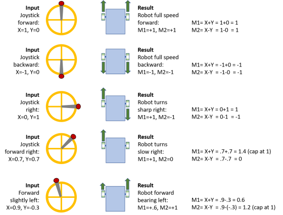
Here is the full set of joystick positions and motor movements that we considered, showing how the equations work:
We previously figured out how to control motors with a H-bridge controller from an Arduino: https://coderdojoathenry.org/2019/02/07/hackers-controlling-robot-wheels-and-handling-interrupts-in-arduino/
Each motor needs two control signals in the range 0-255, one for forward and one for reverse, so we will need more code to convert our M1 and M2 to what is needed for the H-bridge, but that is a fairly easy job for a different day.

Pingback: Hackers – How to Steer an Autonomous Wheeled Robot to Drive Towards a Detected Object | CoderDojo Athenry
Pingback: How to Steer a Robot Car based on Joystick Input or Object Tracking | galweejit
Hello Michael, I am currently working on a same working princible project for a while. I writed a code that has similar working princible as yours. I will check your code and mine to determine whether mine or yours better. Good works topic btw, thanks… taylan.koll@gmail.com
I analyze your princible but I guess your project for only digital output. 0 or 1. I am currently working on analog output for the wheels which can operate the velocity. But your visualizing the princible on the board is very good, it gave me some new ideas about the way I work, thanks…
Thanks for your comment. The calculations as described in the post are indeed for analog outputs, where values are anywhere in the range -1 to +1. -1 is full speed backward, 1 is full speed ahead, and for example 0.5 is half speed ahead.