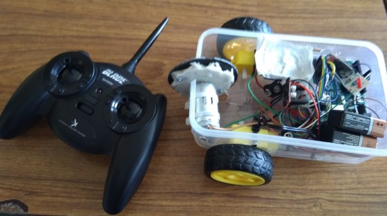
Here is a video of the first tests of our remote-controlled robot with 2-wheel drive.
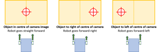
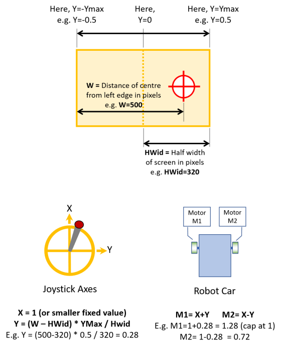
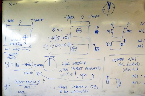
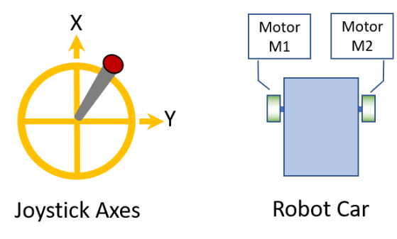
The control for this is based on the calculations we described in an earlier post: https://coderdojoathenry.org/2019/02/24/hackers-how-to-control-a-robots-wheel-motors-based-on-joystick-movements/
Here is the code:
// Code by Luke Madden, CoderDojo Athenry, with some comments added by Michael.
// This code controls a robot with 2-wheel drive, based on movements of a joystick.
// These are the motor H bridge control pins
#define in1 8
#define in2 9
#define in3 10
#define in4 11
// These hold values read from channels of the LemonRX receiver
int ch1;
int ch2; // not currently used
int ch3;
// These are the min and max values we read on each channel when we move the joystick
int joymin = 950;
int joymax = 1950;
// X and Y are joystick values in range -1 to +1
float X;
float Y;
// M1 and M2 are values for Motors 1 and 2, in range -1 to +1
int M1;
int M2;
void setup() {
pinMode(5, INPUT);
pinMode(6, INPUT);
pinMode(7, INPUT);
Serial.begin(9600);
}
void loop() {
// read pulse width values from each channel of lemonRX
ch1 = pulseIn(5, HIGH, 25000);
ch2 = pulseIn(6, HIGH, 25000);
ch3 = pulseIn(7, HIGH, 25000);
// Convert them to floats in range -1 to 1: map uses int, so set it to int in range -1000 to 1000 and then divide by 1000.0
X = map(ch1, joymin, joymax, -1000, 1000)/1000.0;
Y = map(ch3, joymin, joymax, -1000, 1000)/-1000.0;
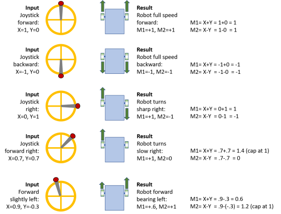
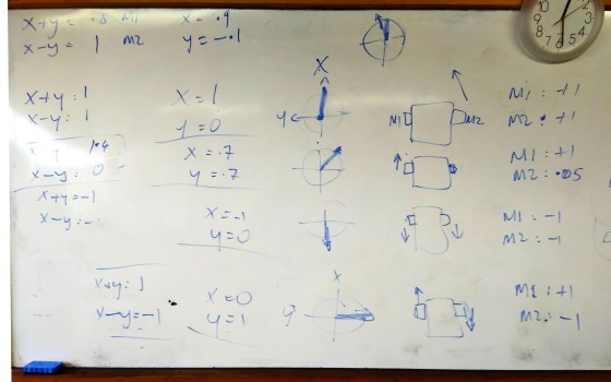
// This is the fomula for how much power to send to each motor
// Motor values should be in range -255 to 255, not -1 to 1, so multiply by 255
M1 = (X + Y) * 255;
M2 = (X - Y) * 255;
// Our fomula can end up with values greater than 255, so constrain them to this range
M1 = constrain(M1, -255, 255);
M2 = constrain(M2, -255, 255);
// Call our function to actually drive the motors
drive(M1,M2);
// print out for debugging
Serial.print("Channels: C1=\t"); // Print the value of
Serial.print(ch1); // each channel
Serial.print("\t M1=\t");
Serial.print(M1);
Serial.print("\t M2=\t");
Serial.print(M2);
Serial.print("\t C3:\t");
Serial.println(ch3);
// this delay seems to help reading joystick
delay(300);
}
void drive(int M1, int M2) {
// drive both motors at speeds M1, M2 in range -255, 255
if (M1 > 0) {
analogWrite(in1, M1);
analogWrite(in2, 0);
}
else {
analogWrite(in1, 0);
analogWrite(in2, -M1);
}
if (M2 > 0) {
analogWrite(in3, M2);
analogWrite(in4, 0);
}
else {
analogWrite(in3, 0);
analogWrite(in4, -M2);
}
}