Notes for weeks 9-12 covering the creation of the lantern, candle, lantern stand and tree.
Copies of files can be found on our Github.
Notes for weeks 9-12 covering the creation of the lantern, candle, lantern stand and tree.
Copies of files can be found on our Github.
This week we:
Moving Enemy from Area2D to AnimatableBody2D
It was necessary to move the enemy from an Area2D based node to a physics body of some sort. AnimatableBody2D is intended for physics bodies that are moved with animation or code.
To change the type of the Enemy node, we right-clicked on it and choose “Change Type”. We then searched for AnimatableBody2D.
Moving code from Mover.gd to Enemy.gd
We added new script directly to the Enemy’s root node, called Enemy.gd. We copied all the code from Mover.gd with the exception of the line “extends Area2D” at the very top and pasted it into Enemy,gd overwriting everything except the very first line, “extends AnimatableBody2D”.
We copied the variables from Mover in the inspector, and assigned the same values to the variables in Enemy.
Testing we found that this worked a bit, bit there was weird effects. It was moving the player too, for example. We recalled that Mover.gd was designed to move the parent of the node it was attached to. For Enemy, that is the scene root, and not what we want. We removed the variable storing the parent and all reference to it, setting our own position instead,
Additionally, we noted that the node called Mover, with a Mover.gd script attached, was still part of the Enemy node tree. It would also be moving our enemy, which we didn’t want. We deleted this node from the tree.
Now when we tested, we found that the the enemy was more-or-less behaving as before, excepting that it was wiggling about. Disabling “Sync to Physics” in the inspector resolved that.
Improving the Code so that Enemy Behaves as a Physics Object
Since AnimatableBody2D is a physics object, we could improve how we were moving it.
With physics objects, we don’t normally set the position explicitly, we set a suggested position, or a suggested velocity and let the physics engine then influence the actual outcome.
To move towards that change, we added a new function _physics_process() and moved the last line of _process() into it, changing position (explicit) to global_position (suggested). We also changed position to global_position in the bounds checking code. The last line in _physics_process() is a call to move_and_collide() which is passing control to the physics engine, once we’ve made our suggestion on position:
func _process(delta: float) -> void:
	wander_change_dir_time -= delta

	if (wander_change_dir_time < 0):
		pick_random_direction()
		set_wander_change_dir_time()

func _physics_process(delta: float) -> void:
	global_position += direction.normalized() * speed * delta
	move_and_collide(direction)
What we then noted, was that the AnimatableBody2D respects collisions with other physics bodies, so the bounds checking that we had previously in Mover.gd was no longer necessary to prevent the enemy moving out of bounds, so we removed exported variable bounds and the function check_pos_for_bounds().
Even though the Enemy was constrained to stay within the play area by the walls around the edge, there was no way yet for it to automatically reverse direction on hitting a wall (or other physics body). We added the following code to _process_physics() to achieve this:
func _physics_process(delta: float) -> void:
	global_position += direction.normalized() * speed * delta
	var collision = move_and_collide(direction)
	if (collision):
		var collision_pos = collision.get_position()

		if (direction.x < 0 && collision_pos.x < global_position.x):
			direction.x = 1
		if (direction.x > 0 && collision_pos.x > global_position.x):
			direction.x = -1

		if (direction.y < 0 && collision_pos.y < global_position.y):
			direction.y = 1
		if (direction.y > 0 && collision_pos.y > global_position.y):
			direction.y = -1
Creating Collision Layers
Objects that can collide with other objects have layers and layer masks:
Imagine these scenarios:
We established these layer:
We moved our player, enemy and boundary walls into their appropriate layers and set their layer masks. The player (ship) is in layer 1 and it’s mask is set to 2, 3, 4.
New Code for Body-on-Body Contact
In ship.gd we could now add code to detect body-on-body contact:
func _physics_process(delta: float) -> void:
	var mouse_pos : Vector2 = get_viewport().get_mouse_position()
	var ship_to_mouse : Vector2 = mouse_pos - position
	var distance : float = ship_to_mouse.length()

	if (distance > DEADZONE):
		velocity = ship_to_mouse * speed_by_distance
	else:
		velocity = Vector2.ZERO

	move_and_slide()

	for i in get_slide_collision_count():
		var collision = get_slide_collision(i)
		var collision_obj = collision.get_collider() as CollisionObject2D
		if (collision_obj && \
			collision_obj.get_collision_layer_value(2) == false):
			%GameManager.inform_body_entered(self)
After move_and_slide() above, we can check for collisions. We need to take any collisions that are not with objects in layer 2 (the boundary layer) and inform the name manager that we’ve hit something we shouldn’t.
Adding Sound when we Shoot
We went to freesound.org to look for suitable sound effects for our Ship when it shoots. Note that the site requires an account before it allows downloading.
We then added a new AudioStreamPlayer2D under Ship and called it ShootSound. Dragging it into the top of the Ship.gd script and pressing CTRL before releasing the mouse button provided this reference:
@onready var shoot_sound: AudioStreamPlayer2D = $ShootSound
In _process() after we’ve created the missile, we just have to insert this line to get the sound to play:
shoot_sound.play()
Getting the Code
All our code for this year is available on our GitHub.
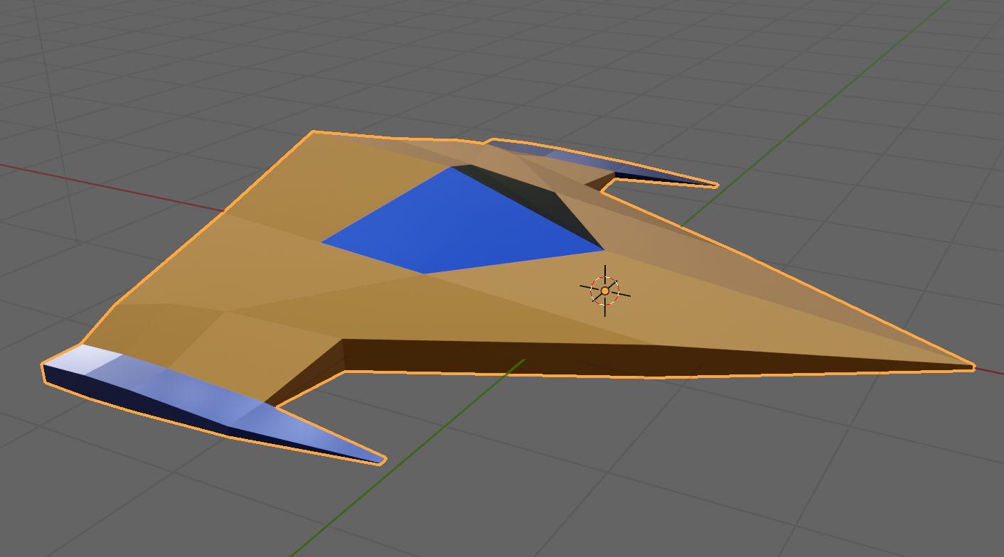
This week we completed our ship from the previous week by adding some materials. Materials are what provides colour to models.
Out model, by default, contains a single material slot. This default material is a grey material and because there’s a single slot, it’s applied to all faces.
To start colouring our model we went to the material properties panel on the right-hand-side of the screen. It has a red circular icon as seen at (1) below.
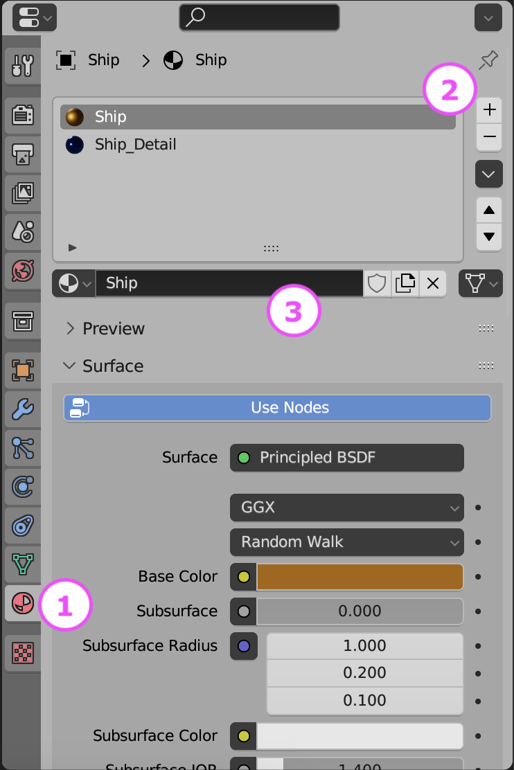
We removed the default material slot by using the – key at (2) above then then added two new materials, called Ship and Ship_Detail by pressing + at (2) to make two new material slots and using the “New” button at (3) when those empty slots where selected to actually make a new material.
The default material component has a lot of inputs, but we can ignore most of them for now. The most important ones are:
We set Ship and Ship_Detail with contrasting colours, metallic finish and low roughness.
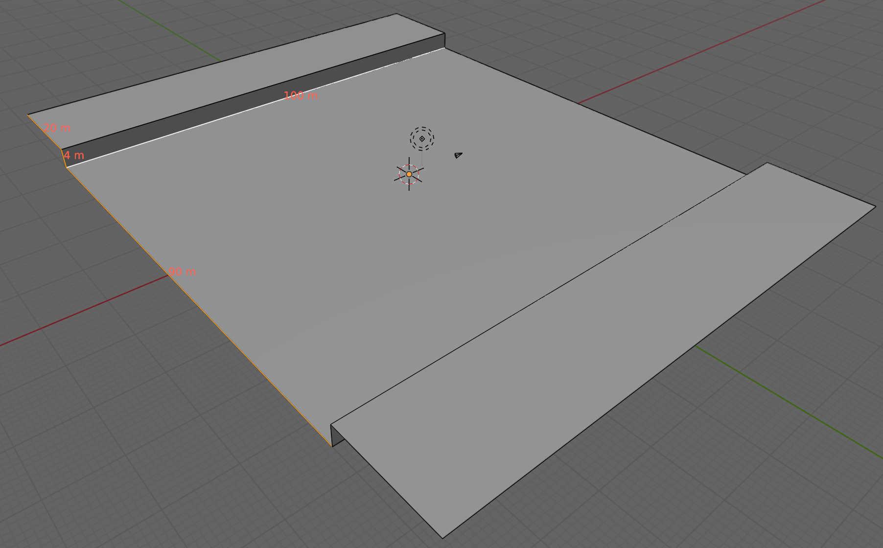
We are going to create loads of environment sections that snap together. The follow the basic pattern show above. A flat area 90x100m in size, with a vertical edge 4m high and a 20m flat area beyond that. We can add any embellishments to the raised flat area on the sides, so long as they’re not too high on the side facing the camera. We don’t want to obscure the ship.
Like the ship, we created two contrasting materials for the environment, one dark as a base and one bright as a contrast colour for details.
The Blender model for this week can be downloaded from our Teams site here.

This week we worked on our gem detector. We want a signal that behaves like this:
To develop the sensor, we created a new test scene. It consists of a flat plane, a tall and narrow cube to represent our target (signal source) and the prefab containing the first person character controller.

We also added a new script ProximitySensor.cs to our Scripts folder and attached it to an empty object in our new scene as “Proximity Sensor”.
We added a few Text – TextMeshPro objects to our scene. Adding the first one automatically added a Canvas object as well. In the scene view. the UI elements look enormous, but in the game view, they just overlay the game image.
All of our positions in Unity are stored as Vector3 objects. If you subtract one Vector3 from another the result is also a Vector3 that contains the differences between the two positions. Unity can give us the length of this (or any) Vector3 through it’s magnitude property. The code below shows this calculation and us setting the value of the UI Text element so we can see it:
float distance = (Player.position - Target.position).magnitude;
DistanceTxt.text = "Distance: " + distance.ToString();
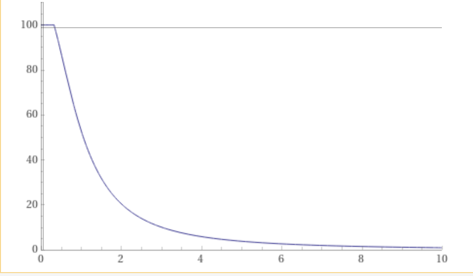
We want a scheme were by the signal falls off quickly with distance. We start with a nominal strongest signal value of 100. If we divide this by distance it falls off, but not that strongly, as shown in the blue line below. If instead we divide it by distance squared (meaning the distance multiplied by itself) the impact of distance is much more dramatic and the value falls off to a small value much more quickly. This is the red line.
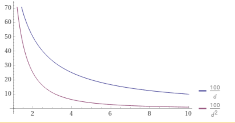
The problem with this scheme is that once distance goes less than 1, the resulting value is greater than 100 and when we get to zero, the value hits infinity (anything divided by zero is infinity).
We can simply solve this infinity problem by adding one to d2. This means that the smallest value it can have is 1, not zero and the highest value the signal strength can get to is 100.

This seems perfect, but actually in testing its clear we can never practically get to zero distance, so we never get to full signal strength. The final modification is not to add one to d2 but to add something a bit smaller. We’re going to use 0.9. Now the signal strength will go as high as 100/0.9 = 111.11 so we just use logic that says if it’s greater than 100, then make it 100. Here’s what that looks like (noting the flat section at the start):
Here’s what the code matching this looks like:
float signalStrength = MaxSignalStrength / ((distance * distance) + 0.9f);
signalStrength = Mathf.Min(signalStrength, MaxSignalStrength);
SignalStrengthTxt.text = "Signal Strength: " + signalStrength.ToString();
A Vector3 that has a length of one is called a “unit vector”. Vector3.normalised gives us back a version of that Vector3 that points in the same direction as the original by always has a length of one.
If we have two Vector3s that have a length of one, we can use the Vector3.Dot() function to determine to what degree they’re pointing in the same direction. Vector3.Dot() also called a Dot Product. When we pass Vector3.Dot() two unit vectors it will return a value between -1 and 1. If the two vectors are pointing in the exact same direction, it will be 1 and if they’re pointing in opposite directions it will be -1. If it’s zero it means that they are perpendicular to each other and don’t point in the same direction at all. Any positive value in-between means they’re pointing in the same direction somewhat.
We can work out the Vector3 from the Player to the Target and the Player’s Forward vector and compare them using Vector3.Dot(). We will make it so that all negative values go to zero. The resulting value is one that gets close to 1 when the player is pointing directly at the target. Here’s the code:
Vector3 playerToTarget = (Target.position - Player.position).normalized;
float pointingTowards = Vector3.Dot(playerToTarget, Player.forward);
pointingTowards = Mathf.Max(pointingTowards, 0.0f);
To combine these calculations, we just multiply them. Now we have a measure that reacts to both distance and direction. Here’s that code:
float adjustedSignalStrength = signalStrength * pointingTowards;
The code for this week’s project is on our GitHub, as always.
Hi Folks. Minimal notes this week as we spent the session working with the sculpting tools in Blender; something you really just need to try for yourself.
To start a new sculpting session, just choose File > New > Sculpting to be presented with a high-resolution quad sphere and an array of sculpting tools.
Of these tools there are three I find most useful:
You should experiment with the others to see which you like best!
Finally, here’s a little rough and unflattering 10min self-portrait I knocked up at the end of the session, just for laughs:
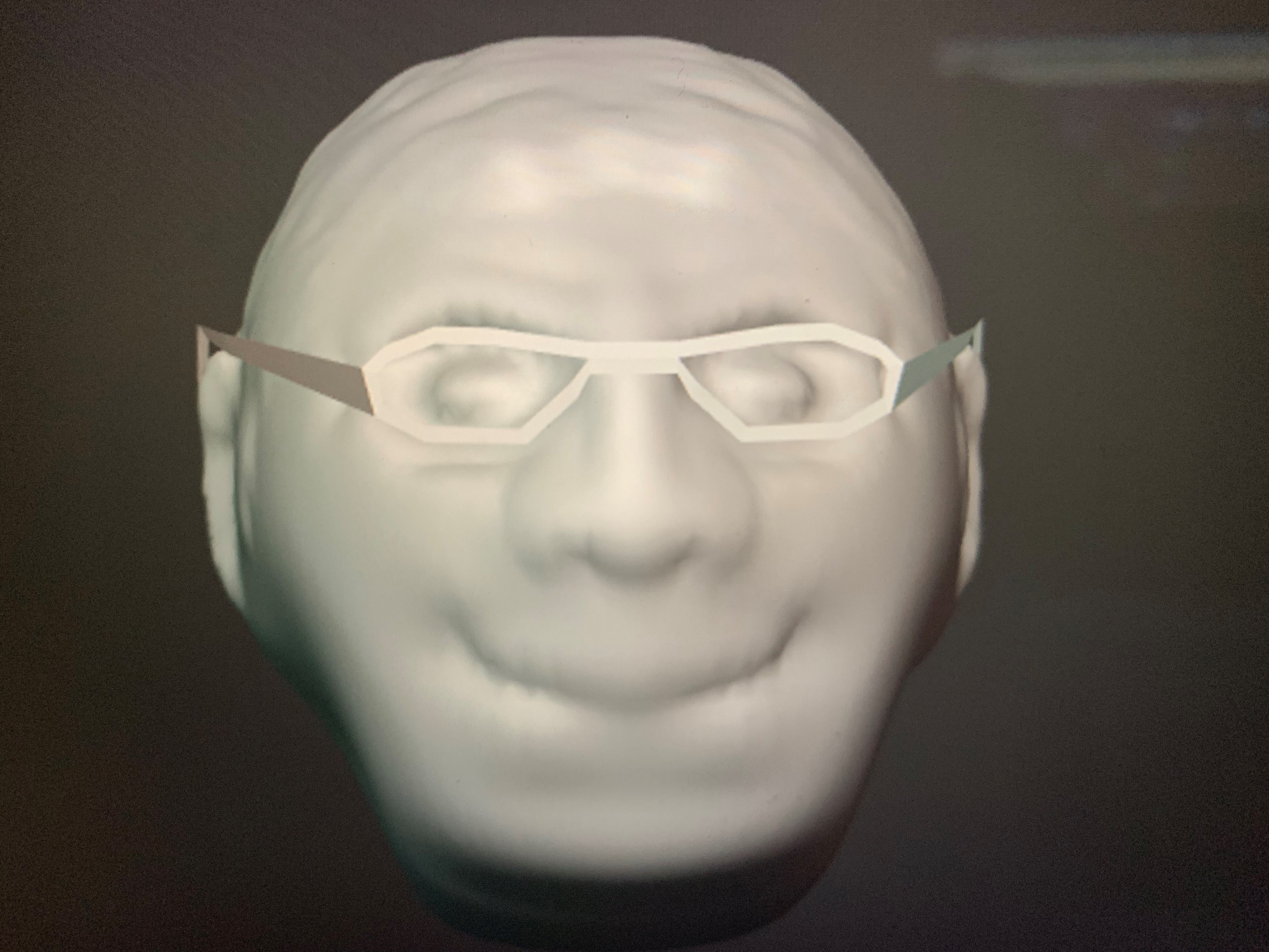
When sculpting, it a good idea to remesh from time-to-time where you’ve significantly deformed the mesh. Remeshing evens the mesh spacing automatically, avoiding places where individual polygons are overstretched, but it’s only available in Blender 2.81. Some people had this version already installed, while others installed it during the session. If you haven’t got it yet and would like to install it you can get it here.
Finally, here’s little personal project you might like to see. I sculpted and painted my cat Noodle’s head. I used a couple of reference photos and a technique called stencil painting to generate the texture:
Thank you so much to Eoin you led the session on Saturday, I think you all enjoyed it. I think you will agree that our two Black Belt Mentors did really well leading their first session. So thank you Ruaidhrí and Eoin
Eoin did a Christmas Scene with you. Here a some screenshots of the code.
See you all on Saturday and Remember bring your own drinks!


Martha
Iseult, Julie, Ruaidhrí and Eoin
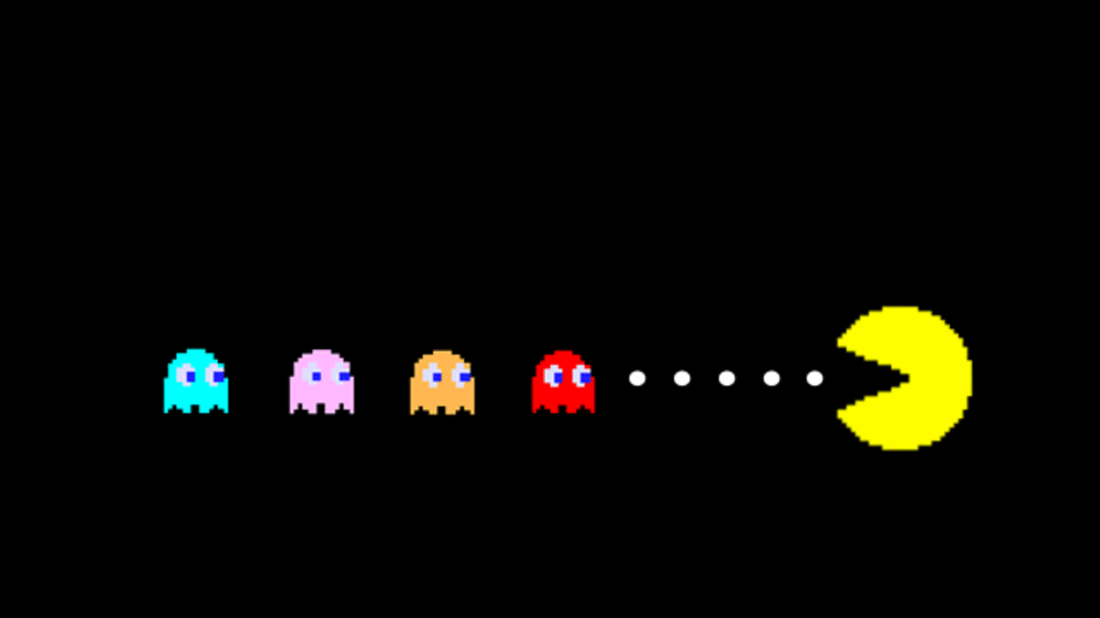 For the last week we worked on a Pacman type game. We tried to put in all the code we have learned over this year and all the games were brilliant and all so different.
This week is our very important week, our last week but the week we award our belts for all your great work during the year. There also might be some Pizza and the odd sausage.
Remember if you haven’t been in the last couple of weeks that doesn’t matter, come along we would love to see everyone.
Here are the notes in PDF CDA-S8 Week_11-PACMA.PDF
See u Saturday
Martha
Julie, Ruaidhrí and Eoin
This week in the Creators group we looked at emulating the classic toy, the Spirograph.
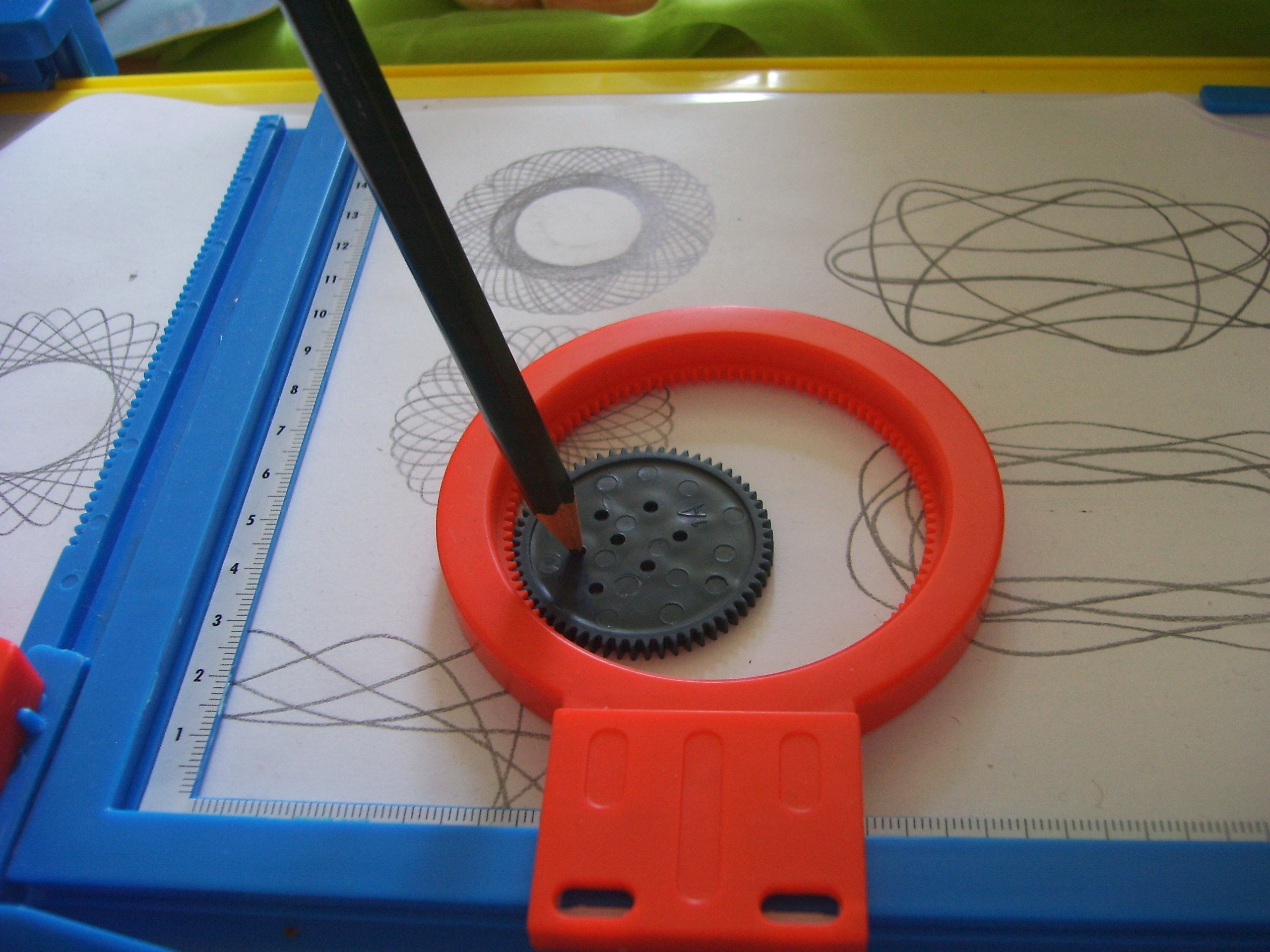
The Spirograph consists of geared plastic discs. One disc is fixed in place over a sheet of paper and the other, with a pencil tracing the path, is allowed to spin around it. The result is a complex and beautiful design on the paper.
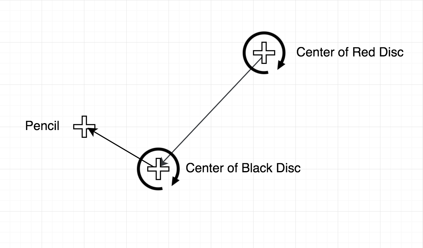
This diagram should help explain in conjunction with the photo. The centre of the black disc spins around the centre of the red disc, which itself doesn’t move. So the centre of the black disc rotates around in a circle. Pretty simple?
Now, the pencil itself rotates around the centre of the black disc. Shouldn’t that make a circle too? Well it would if the black disc wasn’t moving. Thankfully though, it is and that’s what makes this interesting.
Finding the Location of the “Pencil”
So how do we find the location of the pencil? Let’s look at our diagram again, but with things re-labeled a bit:

So at any time the location of our point is:
Point = Centre + [Centre2 relative to Centre] + [Point relative to Centre2]
So know where Centre is and if we can calculate where Centre2 is relative to Centre and similarly where Point is relative to Centre2, we can just add them all together!
Given an angle and a distance, can we get a location?
The answer to this is a resounding “yes”! Look at the diagram:
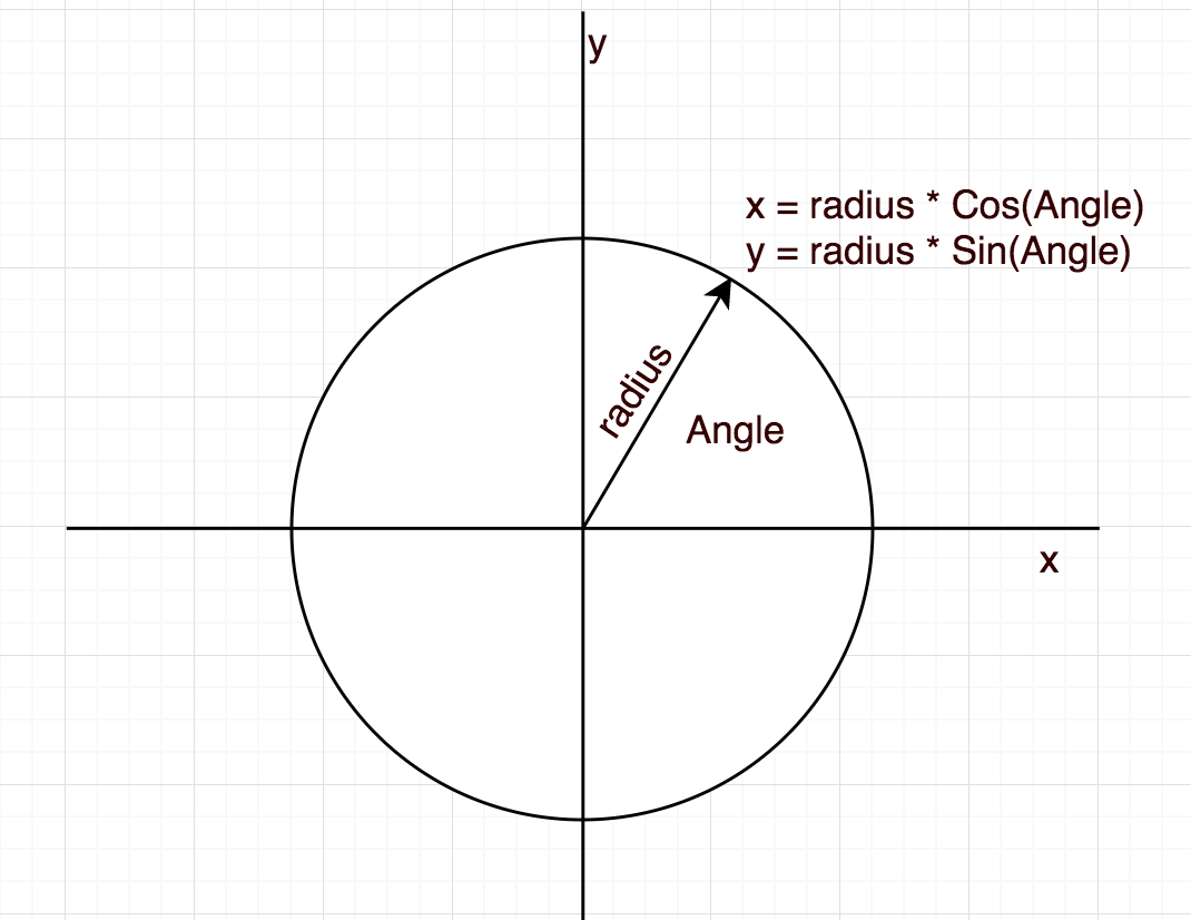
given an angle and a radius, we can calculate the X and Y position of any point around a circle. The magic is the COS and SIN (pronounced “kos” and “sign”) functions. These functions exist in almost all programming languages and JavaScript’s no exception.
Using p5.Vector
The last big concept we tackled thus week was using P5js’s built-in vector class to store (x, y) points and make our code tidier. To make a vector we just use createVector(x, y). We can then use functions to add them together, etc. We would get the same result working with the X and Y values separately but the code is a lot neater and shorter.
And in conclusion
This looks pretty cool:
Getting this week’s code
As aways, all the code from our Creator group can be found on our GitHub repository.
