Hackers – Connect 4 Mechanical Design

This week we looked at the mechanical design for our Connect 4 robot. We need a way to hold the tokens and drop one into a slot when the game-playing AI decides what to play.
We started with two ideas for holding the tokens:

  1. A vertical magazine with 21 tokens held in place by two pins.
  2. A disc holding the tokens at the edge.

The photo below shows an illustration of the magazine idea.

magazine3

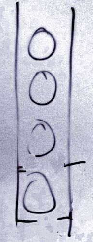
The magazine would move across the board and drop a token into a slot by pulling out the lower pin. The upper pin would hold the rest of the tokens in place so that the wouldn’t drop into the board. Once the bottom token was dropped, the lower pin would be pushed back and the upper pin pulled out to allow the tokens to drop down one step.

The disc idea involved it rotating into place over the board and dropping a token into the board as needed.

We decided that both ideas were impractical on size grounds: the magazine and disc would be very high and hard to support.

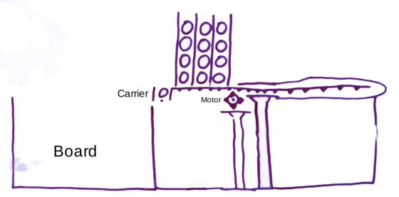
We eventually settled on a modification of the magazine idea: 3 magazines with 7 tokens each. This would be smaller and more stable. It does require us to keep track of the number of tokens in each magazine. That’s something our code should be able to manage.

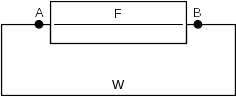
We decided to keep the position of the magazines fixed. A carrier (think cup) could move under the magazine, collect a token and drop it into the board. The magazine and carrier would both need a single pin at the bottom to hold the tokens in place. The carrier should be the height of a single token, so that only one can drop into it. The carrier would have an arm (like a handle) that sits on the magazine side and holds the other tokens in position.

We spent some time discussing how to move the pins in and out before one ninja had a great idea: the pin should be the arm of a servo motor. The servo can rotate the arm through 90° to allow a token to drop.

We then considered how to move the carrier back and forth. We settled on having a single stepper motor drive a gear on a rack that holds the carrier. Turning the gear moves the rack and the carrier into position. Keeping track of the carrier position might be difficult. The easiest way would be to measure the time it takes to reach a particular slot and then power the motor for that amount of time. The problem with that is that it depends on the motor always taking the same amount of time to reach a slot. The motor might slow down as the battery driving it runs down. Mentor Declan suggested using a beam sensor to locate the correct position. We could put a marker above each board position and stop the motor when the sensor reaches the marker. That marker could be something as simple as a small hole. If the beam shines through the hole instead of reflecting, the mark has been found.

Lastly, we considered how to hold everything in place. We think that a large piece of plywood should do the job. We can also attach a sheet of paper to the plywood behind the board to help the vision system see the empty slots. Mentor Kevin pointed out that anything in the background of the board with the same colour as the tokens could confuse the vision system.

The photo below shows a sketch of the final design.

final_design

So, where will the parts from our design come from?
We have an old flatbed scanner that we can scavenge parts from. It has a gear and rack system to move the scan head. It should be long enough to meet our needs. We haven’t looked at the motor that drives the gear yet. We will have to figure out if we can power it and control it. If not, we have motors from previous projects that we can use. The gear probably won’t fit one of the old motors, so we will have to modify it. Or, we can 3D-print a part that will allow us to fit the gear to the motor. That worked well for us last year when we made axles to allow us fit wheels to the motors we had for our hide and seek robots.
We will have to 3D-print the carrier. It will probably take a few iterations to get something that works. It will need to be the right size to hold only one token, and be shaped to stop tokens from dropping lightly and getting wedged. Some experimentation will be needed. We can 3D-print the magazines as well, or maybe make something from plywood strips and cardboard.
We will also need to make a camera mount for our vision system. The mount will need to sit in front of the board, out of the way of the human player. It will need to be in a fixed position so that it covers the whole board and allows us to reliably identify token positions. This will probably be a mix of a 3D-printed part and plywood.
We will tackle these tasks at our next session.

SketchUp in a Can

This week we modelled a soft-drinks can in SketchUp.  A typical can is 135mm high and has a diameter of 66mm.
We made the model in two halves with overlapping edges that can be pushed together.
This model could be 3D-printed and used to hold components for one of our electronics projects.  It gave us a feel for using SketchUp and designing our own models.

We drew a profile of one half of a can and extruded that profile around a circle to make the can. We included a lip on the inside of the shell in the profile. The detailed instructions to make the model are here.
One thing we discovered was that we need to delete the face in the circle, leaving just the outline, before extruding.  If you leave the face intact, the extruded model will be missing its bottom face.

Then we made a profile of the other half, with a lip on the outside.  We put the two together in SketchUp to see how they fitted.  Section planes are helpful for this: insert a  section in the vertical plane and move it in and out using the Move tool to see that the lips touch, but don’t overlap.

One ninja had a great idea:  SketchUp allows us to apply materials to faces.  So, he applied a glass texture to the model so that he could see through it and check that it was correct.

The method of drawing the profile in the instructions above is quite laborious.  The intention is to give us an understanding of SketchUp’s inferencing system for drawing in a particular plane and snapping to end-points and mid-points.  Our ninjas were able to construct the profile much quicker by drawing two touching rectangles, and then removing a section (to make the lip) with a third rectangle.

Next week, hopefully, we will try printing our models on the 3D printer to see how they look.  Our 3D printer software needs a file in STL format to print.  SketchUp doesn’t support STL out of the box. There is an extension in the 3D Warehouse that lets us export our model to STL, so we have to install that first.

Hackers – blinky lights

Today we built our first circuits on a breadboard.

A breadboard is used to try out electronic circuits and figure out what works.  Once we are happy with a circuit we can make a permanent version on something like strip-board.

Breadboards have blue and red lines across the top and bottom.  A wire strip runs across the board under each line.  If we connect a power source to any point on the lines, all of the points (holes) on the line receive the power.

The middle area of the board has wire strips running vertically.  A wire strip runs down the board under each line of holes.  If we connect a power source to any point on the lines, all of the points (holes) above or below receive power.

The first circuit was one to power a single LED:

circuit01_bb.png
We used the Arduino here as a simple 5V battery.  Current flows from the 5V pin on the Arduino, through the resistor, then the LED, and on to the GND pin on the Arduino.  We should always used a resistor with an LED to protect it.  It doesn’t take much current to damage an LED.

This has the LED on permanently – not very exciting, but good to get started with.  It’s a good idea to start with a minimal circuit and build up to the more complicated circuit we actually want.  That way, we can test and verify as we go, so that we don’t have too much testing and backtracking to do if something goes wrong.

It took a while to get everyone’s circuit working.  Some of the LEDs had legs that were the same length, and there was no obvious way to see which one was the anode or cathode, so we had to guess and test.
Some of the resistors we took at random from the box were too high:  200 kΩ, for example, so the LEDs wouldn’t light up.  We found some 220 Ω (red-red-brown) and 330Ω (orange-orange-brown) resistors to get us going.
Some of the LEDs were very dim.  180 Ω resistors (brown-grey-brown) helped there.
We did a quick calculation to see what value of resistor we really needed:

According to the spec sheet, our LEDs had a forward voltage of 2.2 V and a forward current of 20 mA. In other words, the voltage drop across the LED is 2.2 V, and they can draw up to 0.02 A without burning out.
If our supply is 5 V, then the voltage across the resistor is 5 – 2.2 = 2.8 V.  This is Kirchoff’s Voltage Law.
Applying Ohm’s Law (V = RI), 2.8 = R*0.02, so R = 2.8/0.02 = 140 Ω.
A 140 Ω resistor will make our LED as bright as possible. Less than that will burn out the LED. More than that will produce a dimmer light. So, 180, 220, and 330 Ω are all fine.
Different LEDs have different forward voltages and currents, so it’s important to keep and consult the specification sheets before using them.

The next step in our circuit building was to connect the Arduino’s ground pin to the ground rail on the breadboard.  Then we connected the negative (cathode) pin of the LED to the ground rail.  This is an important step in circuit building:  using a common ground for all our circuits on one board.  It allows us to only have one wire running back to the Arduino ground, instead of one for each circuit.  We would run out of space on the Arduino very quickly otherwise.
Next we did the same on the positive side. This isn’t necessarily as useful as the common ground as we’ll see later.

Once we were happy that we all had a working circuit, we moved on to use the Arduino to control the LED.
We did this by taking the wire that went to the 5V pin on the Arduino and plugging it into digital pin 12 instead.  We went back to our Arduino sketches and defined a new integer variable, ledPin, and gave it a value of 12 to match where we plugged it in.
Then we changed every occurrence of LED_BUILTIN in our sketches from last week to ledPin instead.  The Find (Replace with) function on the Edit menu of the IDE was helpful here.

Once we compiled the sketch and uploaded it to the Arduino, we had the LED on
the breadboard blinking our messages, just like the internal LED was last week.

Next, we added a second LED and resistor to the board, and wired it up the same as the first.  The positive side of the resistor was connected to the positive power rail, and from there on to the Arduino. Now both LEDs blinked together.
To get them to blink separately, we took the wire from our second LED going to the positive rail and plugged it into digital pin 8 on the Arduino.

circuit06_bb.png

Then we created a new variable in our sketch, led2Pin, with a value of 8.
We added setup code for pin 8.  Finally, we added two more lines to the loop, to have the output to LED 2 go low after LED 1 was set high, and vice versa.
The outcome was LED 2 was on when LED 1 was off and LED 2 was off when LED 1 was on.
Some demonstration code is shown below.

// Blink 2 LEDs: one on, one off
// Demonstration for CoderDojo Athenry

int led1Pin = 12;
int led2Pin = 8;

int one_second = 1000;  // delay() function expects milliseconds

void setup() {
  pinMode(led1Pin, OUTPUT);
  pinMode(led1Pin, OUTPUT);
}

void loop() {
  digitalWrite(led1Pin, HIGH);  // on
  digitalWrite(led2Pin, LOW);
  delay(one_second);
  digitalWrite(led1Pin, LOW);  // off
  digitalWrite(led2Pin, HIGH);
  delay(one_second);
}

Hackers – Hide and Seek

We welcomed back Hackers Group members Luke and Sean, who had projects at the Young Scientists Exhibition last week.  Details of their projects are in another post: Congratulations to our members who presented at the BT Young Scientists 2019!

This week we divided the group into two teams to work on our hide-and-seek robots:  One team to build the hider robot, the other to build the seeker robot.

The two robots can use many of the same parts, but the control systems will be different.  The hider robot will be operated by a person with an RC transmitter.  The seeker robot will control itself.

Team Hider started resurrecting a radio-controlled robot that we built last year.  The robot was involved in a battle-bots battle at the end of the year, so it is in pretty poor shape.
Teem Seeker worked on a colour tracking system.  We took the code that we developed on a laptop before Christmas and tried it on two Raspberry Pis.  We found that the original model Raspberry Pi wasn’t fast enough to do the job we needed.  It took 6 seconds to acquire an image from a webcam.  We tried a Model 3 B instead.  This was fast enough for our needs.  We then started work on tuning the colour detection.  There’s some more experimentation to be done to find the best colour range to work with.

Hackers – Starting with object recognition

This week we looked at two ways to do object recognition.

Kevin went through the steps involved in finding an object with a particular colour in an image.  He started on an image with six circles each of a different colour, and demonstrated finding a green circle in the image.  Then he stepped through the Python code and explained each task.

Here’s the image:

circles_small

OpenCV, the Open Source Computer Vision library, has lots of functions for transforming and processing images.

We started with a standard RGB (red, green, blue) JPEG image, which OpenCV stores in memory as BGR (blue, red, green).  Then we transformed the image to HSV (hue, saturation, value) format.  The HSV colour space has a very useful property:  colours are described by their hue and saturation.  The value represents the intensity of the colour.  This means that we can use H and S to find a colour, without having to worry much about lighting or shadows.

Next we used the known value for the green circle to apply a threshold to the image:  any colours above or below the threshold are converted to black.  Any colour at the threshold is converted to white.  Here’s what the thresholded image looked like:

threshold_small

Then we found the white area in the image.  To do that, we used an OpenCV function that gets the co-ordinates for contours that can be drawn around the boundaries of all the white regions in the image.  We calculated the areas of each contour, and took the largest.  We’ll find out why this is useful later.

To show that we had found the right circle, we calculated the co-ordinates of its centre-point.  Finally, we drew a small cross at that centre-point to mark it, and displayed the full image on screen.  This is what we ended up with:

green_smallSince we had a contour, we also used that contour to draw a line around the perimeter of the circle.

Next, we took a photo of a blue marker, found the HSV value of the blue, and used that value to find the marker in a live image.  We held the marker in front of a laptop webcam, moved the marker around, and watched as the spot moved with it.  Our method for finding a particular colour works for any shape, since we use a contour, not just circles.

Michael introduced us to TensorFlow, a machine learning library.  Once trained, TensorFlow can identify specific objects by name.  It’s a lot more sophisticated than finding something by colour.  We spent some time setting the library up on a Raspberry Pi.  The Pi isn’t powerful enough to train the software, but it is capable of doing the recognition after training models on more powerful computers.

Or final goal is to build an autonomous robot to play a game of hide and seek.  We can use one of our remote-controlled battlebots from last year to hide, and the new robot to do the seeking on its own.  One way to do the seeking would be to go after the biggest thing in the robot’s field of view that has a particular colour – the colour of the hiding robot.  Another way to do the seeking would be to train a TensorFlow model with pictures of the hiding robot, so that the seeker can recognise it from different angles.

It’s going to take us a while to figure out what works best, and then we have to work out how to control our robot.  It should be an interesting new year.

Hackers – Temperature Control, Part 2

Today we continued towards building a temperature controller.

Last week, we used an LM35 temperature sensor to read the temperature in the room and report it on the Arduino serial console.
We were able to get a reading for the temperature of the air in the room, and the temperature of a cup of coffee touching the sensor.  We couldn’t be sure, however, that the readings were correct.  So, we decided to test with a potentiometer and a voltmeter.

We supplied 5 V to the potentiometer and fed the output to the Arduino.  We used a voltmeter to measure the output from the pot and compared it to the reading from
the Arduino.  Once we got the code working, we got good agreement on voltage readings between the meter and the Arduino.

The sensor presents a voltage on its output pin that represents the temperature its measuring.  In its basic mode, the sensor reads temperatures between 0.2 and 150 degrees Celsius.  Every degree is 10 mV, so the output voltage ranges from 2 mV to 1500 mV.  Converting our voltage reading to a temperature is simple then:  divide the voltage reading in millivolts by 10.

We can use one of the analog I/O pins on the Arduino to read the voltage.  The analogRead() function returns a value between 0 and 1023 for voltages between 0 and 5 V.

We digressed into how to use a multimeter correctly.  The first thing to do is make sure that our meter is set up correctly.
We tried measuring a 9 V DC battery with the DC voltage setting and got 9.2 V.  We then tried measuring the same battery with the AC voltage setting.  This time we got 19.6 V.
There’s a lot of potential (sorry) to get confused, then.  Worse again, if we try measuring 220 VAC with the meter set to DC, we get a reading close to zero.  In other words, a live AC supply looks safe if we set our meter wrong.

Next, we start with the highest reading range and step down.  For a 1.5 V battery, we start with the 200 V reading, then step down to 20 V.  This is to protect the meter:  if the voltage is higher than we expected, we might damage the meter.

Voltage readings are taken in parallel with the circuit, and while it is live.

Resistance and continuity readings, on the other hand, are taken with the component disconnected from the circuit.
We worked out why with a simple circuit:

circuit1

F is a fuse.  W is a wire between the two ends.  We’re not sure if the fuse is blown.  We try testing for continuity across the fuse by putting our meter leads on A and B.
Even if the fuse is blown, we will get continuity because W provides a circuit.  We need to cut the wire to get a true reading.

Our first attempt at Arduino code for the voltage reading gave us a surprise.  Our meter displayed 2.5 V.  The Arduino displayed 2 V.  We used this formula to calculate the voltage:
v = 5 * analogRead_reading / 1023.
V was declared as float variable.  analogRead_reading was declared as an int.  The Arduino code multiplied two ints and divided the result by another int, truncated the result and stored the int as a float.  When we made the 5 and 1023 floating point numbers (5.0 and 1023.0), we got the right answer.

Once we were happy with the Arduino code, we replaced the potentiometer with an LM35.  Unfortunately, we didn’t notice the “bottom view” label on the datasheet drawing.  We connected the 5 V supply to the wrong side of the sensor.  It’s amazing how hot a temperature sensor can get!  It was too hot to touch.  And we couldn’t measure the temperature because…
After we disconnected the LM35, we made another discovery:  we continued to get random voltage readings displayed on the Arduino even though there was no voltage to read.  The analogRead() function happily outputs values from random noise.

Next week, we’ll use an LM35 connected the right way around, and try controlling a relay to switch power on and off to an external device.  We’ll build a temperature controlled soldering station carefully – we want to solder with the tip of the iron, not the temperature sensor.