Today we continued towards building a temperature controller.
Last week, we used an LM35 temperature sensor to read the temperature in the room and report it on the Arduino serial console.
We were able to get a reading for the temperature of the air in the room, and the temperature of a cup of coffee touching the sensor. We couldn’t be sure, however, that the readings were correct. So, we decided to test with a potentiometer and a voltmeter.
We supplied 5 V to the potentiometer and fed the output to the Arduino. We used a voltmeter to measure the output from the pot and compared it to the reading from
the Arduino. Once we got the code working, we got good agreement on voltage readings between the meter and the Arduino.
The sensor presents a voltage on its output pin that represents the temperature its measuring. In its basic mode, the sensor reads temperatures between 0.2 and 150 degrees Celsius. Every degree is 10 mV, so the output voltage ranges from 2 mV to 1500 mV. Converting our voltage reading to a temperature is simple then: divide the voltage reading in millivolts by 10.
We can use one of the analog I/O pins on the Arduino to read the voltage. The analogRead() function returns a value between 0 and 1023 for voltages between 0 and 5 V.
We digressed into how to use a multimeter correctly. The first thing to do is make sure that our meter is set up correctly.
We tried measuring a 9 V DC battery with the DC voltage setting and got 9.2 V. We then tried measuring the same battery with the AC voltage setting. This time we got 19.6 V.
There’s a lot of potential (sorry) to get confused, then. Worse again, if we try measuring 220 VAC with the meter set to DC, we get a reading close to zero. In other words, a live AC supply looks safe if we set our meter wrong.
Next, we start with the highest reading range and step down. For a 1.5 V battery, we start with the 200 V reading, then step down to 20 V. This is to protect the meter: if the voltage is higher than we expected, we might damage the meter.
Voltage readings are taken in parallel with the circuit, and while it is live.
Resistance and continuity readings, on the other hand, are taken with the component disconnected from the circuit.
We worked out why with a simple circuit:
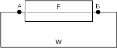
F is a fuse. W is a wire between the two ends. We’re not sure if the fuse is blown. We try testing for continuity across the fuse by putting our meter leads on A and B.
Even if the fuse is blown, we will get continuity because W provides a circuit. We need to cut the wire to get a true reading.
Our first attempt at Arduino code for the voltage reading gave us a surprise. Our meter displayed 2.5 V. The Arduino displayed 2 V. We used this formula to calculate the voltage:
v = 5 * analogRead_reading / 1023.
V was declared as float variable. analogRead_reading was declared as an int. The Arduino code multiplied two ints and divided the result by another int, truncated the result and stored the int as a float. When we made the 5 and 1023 floating point numbers (5.0 and 1023.0), we got the right answer.
Once we were happy with the Arduino code, we replaced the potentiometer with an LM35. Unfortunately, we didn’t notice the “bottom view” label on the datasheet drawing. We connected the 5 V supply to the wrong side of the sensor. It’s amazing how hot a temperature sensor can get! It was too hot to touch. And we couldn’t measure the temperature because…
After we disconnected the LM35, we made another discovery: we continued to get random voltage readings displayed on the Arduino even though there was no voltage to read. The analogRead() function happily outputs values from random noise.
Next week, we’ll use an LM35 connected the right way around, and try controlling a relay to switch power on and off to an external device. We’ll build a temperature controlled soldering station carefully – we want to solder with the tip of the iron, not the temperature sensor.
