Hackers – Soldering LED Circuits

At Hackers this week, we learned how to solder. Group members stripped wires and then soldered them together, and they made LED circuits by soldering them onto stripboard, and tested them with Arduino programs.

As we discussed, it is important to build your circuits temporarily with a breadboard (where you just push the wires in, and can easily move them) before moving onto soldering them on to stripboard. Stripboard (also called Veroboard) has holes every 2.5mm in a grid, and has copper strips on one side connecting the holes in one direction. You mount the component (such as an LED on the side with no copper, and solder its pins to the copper strip. Then, you can solder a pin of a different component somewhere else along the same copper strip, and current can flow through the copper strip.

There are plenty of videos on YouTube  to demonstrate soldering technique. Here is one by Emer Cahill of GMIT:

Explorers Week 9 – Guessing Game!

Hello Everyone,

Great to see you all on Saturday.

We made a slight departure from the games we have done in previous weeks. This weeks game was a mathematical Guessing Game.

DUCK

We only had one sprite and one large block of code. We had to create variables and figure out all the possible situations that could occur when a guess was made.

guess

Here are the notes in PDF form from this weeks session CDA-S8-Week_09-GuessNumbers.pdf

Martha

Iseult, Julie, Ruaidhrí and Eoin

Modellers – Week 8

Hi folks.

This week we started looking at texturing. Texturing is the process of taking an image, which is flat, and mapping it onto a 3D object, which generally isn’t.

UV maps are just the plan that shows which part of the texture goes to which part of the 3D model.

Unwrapping is the process of taking the 3D surface of the model and laying it flat, like peeling an orange. This flattened version of the model, when placed over the texture becomes the UV map.

unwrap

The animation above illustrates the process for a simple shape as if we really were unfolding the shape manually. In reality, we just tell Blender where the seams are (where it can cut the model’s surface) and the rest can happen automatically.

Here are the video instructions for this week:

The model file can be downloaded from here.

Next week, we actually paint the model and perhaps add a logo.

Hackers – Getting started with Python programming on Arduino

circuit2

In the past two weeks in the Hackers group at CoderDojo Athenry, we have started Python programming on the Raspberry Pi.

The Pi is about the same size as the Arduino that we used earlier, and the Pi Zero is about the size of the Arduino Nano, and both Pi and Arduino have input/output pins for physical computing. However, they have significant differences.

Unlike the Arduino which is a microcontroller (which means it is designed to run a single program that was uploaded onto it), the Raspberry Pi has a full computer operating system, so it is more like a PC to use. It can be programmed in many languages, but Python is a popular choice as it is clear to read and there are lots of libraries to make tasks easier. Because it’s a full computer, you can write and run your programs all on the Pi, without connecting it to a laptop.

The first step in programming is to figure out how to do loops, variables and decisions, as these are fundamental. Here is our first Python program to try out these:

# Python comments start with #

age = 14 # a variable holding an int
name = "Michael" # variable holding a string

# Output
print ("My name is", name, "and my age is ", age)

# Loop
for x in range (1, 5):
    print ("This is line ", x)

# Decision
if (age  17):
    print("Adult")
else:
    print("Teenager")

Next we moved on to using the GPIOZero libraries for controlling lights and buttons. We will continue to explore this in the coming weeks.

The documentation is here: https://gpiozero.readthedocs.io/en/stable/


Week 8, Explorers – Pen Commands

Hello Everyone,

This week we finished off our Paint Program from last week and did some more work with Pen Commands.


pencommand

We didnt get to do all the code that is in the attached notes so if you want to give it a go yourself, that would be great. You can add a start and stop button and some variables.


sliders


Here are the full Pdf version of my notes from this weeks session. CDA-S8 Week 8-Pen Command.pdf

Hope to see you all this Saturday, we will be doing a great Maths Guessing Game!

Martha

Julie, Iseult, Eoin and Rauidhrí

Week 8 2019 Explorers – Paint Program

Hi everybody,

our drawing program. We made good use of costumes this week to make it look like we were dipping our paint brush in each of the different colours.

We also used a variable similarly to how we used in the Piano Game we made. We made it into a slider and then code select the Pen Size we wanted.

Here are the notes in PDF. CDA-S7-Week_08-Paint.PDF


Martha


Hackers – Distance Sensor

Some of our Hackers have projects of their own that they are working on, to possibly submit to BT Young Scientists or elsewhere. Last Saturday, those people were focused on working on their own project, with occasional help from peers or mentors where needed.

Those who were not working on their own projects extended last week’s Arduino project to add an ultrasonic distance sensor, replacing the variable resistor that they used last week.

Ultrasonic distance sensors are interesting: like sonar in a submarine or how bats navigate, they send out a short sound pulse (ultrasonic – too high for humans to hear) and then see how long it takes for an echo to come back. Since the speed of sound in air is known, we can calculate the distance to the nearest object based on the time for the round trip.

Here is a good tutorial on how it works: https://howtomechatronics.com/tutorials/arduino/ultrasonic-sensor-hc-sr04/

Above is a circuit designed by mentor Kevin for an ultrasonic distance sensor and a buzzer, to work like a car parking sensor that beeps faster as you get closer to an obstacle.

Below is Kevin’s Arduino program to control the distance sensor and print out the distance. Some people in the group modified this to use buzzers, others turned on 1, 2 or 3 LEDs depending on distance. #

const int triggerPin = 12;
const int echoPin = 10;

// The speed of sound in air at standard temperature and pressure is 343m/s.
// The range of the sensor is 4m.  It takes 2*4/343 seconds for an ultrasonic
// pulse to travel that far and back.
// We'll use that as a timeout later.  There's no point in waiting any longer
// than the time it takes to read an object at the maximum range of the sensor.
unsigned long echo_timeout = 2*4000000/343;

void setup() {
 Serial.begin(9600);
 pinMode(triggerPin, OUTPUT);
 pinMode(echoPin, INPUT);
 pinMode(LED_BUILTIN, OUTPUT);
}

void loop() {
  unsigned long duration;
  float distance;

  // Begin by resetting the distance sensor 
  digitalWrite(triggerPin, LOW);
  delayMicroseconds(2);
  // Write out a short pulse for 10 microseconds
  digitalWrite(triggerPin, HIGH);
  delayMicroseconds(10);
  digitalWrite(triggerPin, LOW);
  
  // pulseIn will wait for the input on echoPin to go HIGH.  Then it will
  // time how long it takes to go LOW.
  // The duration in microseconds is returned.
  // We'll wait, at most, echo_timeout microseconds for a pulse. 
  duration = pulseIn(echoPin, HIGH, echo_timeout);
  Serial.print("duration = ");
  Serial.print(duration);
  Serial.print(" microseconds;  ");
  
  // Convert duration to distance. Note decimal point here, needed to get floating point calculation.
  distance = duration * 343.0 / 1000 / 2;
  Serial.print("distance = ");
  Serial.print(distance);
  Serial.println(" mm");
}

Modellers – Week 5

Hi folks, thanks again for another fun session.

This week we continued our sword model. We finished the blade and started work on the guard.

We didn’t introduce any new concepts this week, but we did make our first practical use of the mirror modifier to allow us to create one side of the sword guard and have the other side created automatically.

Here are the video instructions from this week:

The matching model file can be downloaded from here.

Hackers – Basic Arduino inputs and outputs

Rheostat_bb

This week in the Hackers group at CoderDojo Athenry, we built on last week’s work on blinky lights, in which we made a simple circuit involving LEDs and resistors connected to an Arduino, and wrote code to get the LEDs to blink.

An LED is an example of an output from our microcontroller. We would also like to have inputs. Examples of circuit inputs are:

  • Switches
  • Dials
  • Sensors that measure something

We focused on dials, specifically a variable resistor or rheostat. This is the kind of knob or dial you find on dimmer switches, volume controls on old radios, electric guitars, and many others.

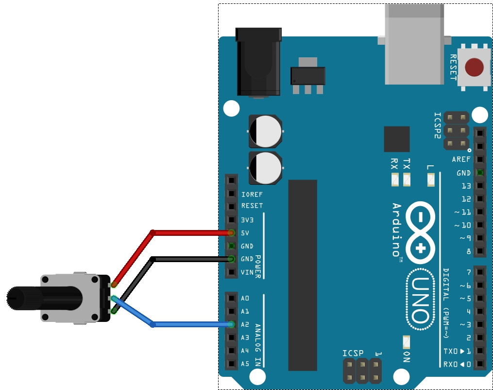
A variable resistor has 3 connectors: the two outer ones connect across a voltage source (e.g. 5V and ground pins on the Ardiuno) and the voltage at the middle pin can be adjusted from 0 to 5V by turning the knob.

We connected the middle pin of the variable resistor to Analog input 2 of the Arduino. The connections are shown above.

Then, the code to read its value is:

potValue = analogRead(potPin);

where potValue and potPin are ints that were defined already.

The value that you get is in the range 0-1024, and changes as you turn the dial.

Here is a full Arduino program to read a value and display it on the Serial Monitor window if you have a computer connected to your Arduino:

int potPin = 2;    // select the input pin for the potentiometer
int potValue = 0;  // value to read from potentiometer

void setup() {
  Serial.begin(9600);  // need for print commands later
}

void loop() {
  potValue = analogRead(potPin);    // read the value from the sensor
  Serial.println(potValue);
}

In the group, we used this as the basis to improve last week’s program. This time, the speed at which the LED blinks is controlled by turning the potentiometer dial.

The previous code to control how long the LED blinks for was:

delay(one_second);

We changed this to:

delay(potValue);

Of course, we also had to add the code to read the potentiometer value at the top of the loop() function.