Notes for Week 7:
Final video:
Copies of files can be found on our Github.
We started a new game this week, inspired by the classic Crystal Quest written first for the Macintosh in 1987. Below is a screenshot of a later colourised version:
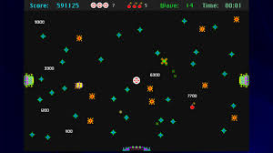
In Crystal Quest, the mouse controls the velocity of a little round ship, you must avoid obstacles and enemies, while collecting all crystals in a level, before making your way safely to the exit to complete a level. As the levels increase, the action gets increasingly intense.
We started a new project called Crystal Quest and chose a new 2D Scene as out starting point. We looked at the layout of the 2D scene and examined the default resolution in the Project Settings.
We renamed the Node2D at the top of our new scene “Main” and saved it to a project folder called “scenes”.
Adding our Ship
We added a CharacterBody2D to the scene and renamed it to “Ship”. It required a CollisionShape2D, we provided one with a CircleShape of 16px radius. This defines the shape of our object, for collision purposes.
We still had nothing we could see. While 3D games require 3D models, 2D games require 2D sprites (images). While Godot has a bunch of simple 3D shapes built-in, there’s nothing equivalent for 2D sprites.
We took a look at a free, online, pixel editing tool called Piskel:
There we were able to generate a 32x32px sprite to represent the ship.

The ship sprite below can be downloaded, if desired:

We exported the file from Piskel as a PNG and saved it to a “textures” folder in Godot. Now that we have this image resource, we were able to add a Sprite2D under Ship. The ship was then visible.
The ship was still at the top of the screen, so we relocated it to the centre. We then added a script to Ship, saving it in a “scripts” folder.
The default script file for a CharacterBody2D is to provide platform character-like movement (left, right and jump, with gravity). We explored this, adding a StaticBody2D and CollisionShape2D the bottom of the screen to catch the Ship before it fell past the bottom of the screen. Once we understood what the old code was doing, we removed all the code from the _process_physics() function except the last line; move_and_slide().
Moving Something Controlled by Physics
When we move something in Godot controlled by physics, we effectively state what we’d like to happen by adding forces to the body, or setting its velocity, but once we call move_and_slide() Godot will take everything that’s happening from a physics viewpoint and take that into account, alongside what we asked for. For example, if we propel our body into a wall, it can’t move through the wall, regardless of how we set the velocity to be into the wall.
Following the Mouse
In the Ship’s script, in the _process_physics() function, we added a couple, of lines. The first finds the location of the mouse pointer and the second sets the ships location to the mouse’s location:
func _physics_process(delta: float) -> void:
	var mouse_pos : Vector2 = get_viewport().get_mouse_position()
	position = mouse_pos
	move_and_slide()
While this seems initially to work, it also allows us to pass beyond the StaticBody2D representing the bottom wall of our game area. Setting the position isn’t what we really want to do. Instead, we set the velocity of the ship to point towards the mouse. This looks like the following:
@export var speed_by_distance : float = 1.0

func _physics_process(delta: float) -> void:
	var mouse_pos : Vector2 = get_viewport().get_mouse_position()
	var ship_to_mouse : Vector2 = mouse_pos - position

	velocity = ship_to_mouse * speed_by_distance
	move_and_slide()
Note also that we’ve added an export variable to control the ratio of speed to distance. This gives the effect that we want, the ship always moves towards the mouse pointer, the speed of movement is proportional to how far away the mouse is.
Sometimes, depending on the mouse or trackpad used, the ship might oscillate wildly once it’s at the mouse pointer’s location (if the mouse pointer is changing very slightly all the time). We can prevent this with a deadzone, as follows:
@export var speed_by_distance : float = 10.0

const DEADZONE : float = 10.0

func _physics_process(delta: float) -> void:
	var mouse_pos : Vector2 = get_viewport().get_mouse_position()
	var ship_to_mouse : Vector2 = mouse_pos - position
	var distance : float = ship_to_mouse.length()

	if (distance > DEADZONE):
		velocity = ship_to_mouse * speed_by_distance
	else:
		velocity = Vector2.ZERO

	move_and_slide()
Now the ship won’t move unless the mouse pointer is more than 10px from the ship’s centre. Note too, that we’ve upped the ship’s speed_by_distance to 10.0.
Hiding the Mouse Pointer
The Operating System mouse pointer is distracting in our game. To hide it, we created a new Node2D as a child of Main and called it “MouseHider”. We added a new script as follows:
extends Node2D

# Called every frame. 'delta' is the elapsed time since the previous frame.
func _process(delta: float) -> void:
	var vp_rect : Rect2 = get_viewport().get_visible_rect()
	var mouse_pos : Vector2 = get_viewport().get_mouse_position()

	if (vp_rect.has_point(mouse_pos)):
		Input.set_mouse_mode(Input.MOUSE_MODE_HIDDEN)
	else:
		Input.set_mouse_mode(Input.MOUSE_MODE_VISIBLE)
This hides the mouse pointer if it’s inside the viewport (screen) and enables it again outside of that.
Getting the Code
All our code for this year is available on our GitHub.
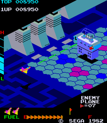
I decided, since we weren’t making a lot of progress with our Dungeon game, that we might need to switch to something simpler. We are going instead to make a game in the style of an isometric side-scrolling arcade shooter. This style of game first appeared back in 1982 with Sega’s Zaxxon (pictured below) but there have been many examples since.
We decided to call our game “Speedy Spaceship”.
To start with the game we opened a new Unity project and used the Package Manager to install the new Unity Input Manager package. This is the preferred way to define user inputs in Unity these days as it’s far more flexible when you want to add alternative control schemes (gamepad instead of keyboard, for example).
We first created a folder called Input and in there we made a new “Input Actions” asset and called it “ShipControls”. Opening this, we defined a simple control scheme, for keyboard and mouse, as follows:
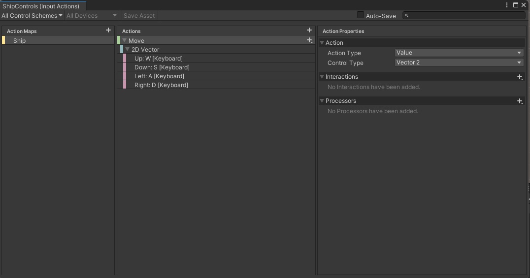
At the moment it only contains one action “Move” but we’ll be adding at least one more action later to enable shooting. Movement is bound to the WASD keys on the keyboard.
Once we’d done that, with this Input Actions asset still selected in the Project view, we selected the “Generate C# Class” option in the Inspector and pressed the “Apply” button. This made a script file called “ShipControls.cs” next to our Input Actions asset in the inputs folder. This file contains a lot of code for handling the interactions, but we don’t need to worry about it’s contents; it’s easy for us to make use of it.
We then added a plane, which we added a material to, and a cube positioned just above the plane, to our current scene. With the cube selected, we positioned ourselves in the Scene View such that the cube’s X-axis (red) was pointing right and away from us and the cube’s Z-axis (blue) was pointing left and away from us.
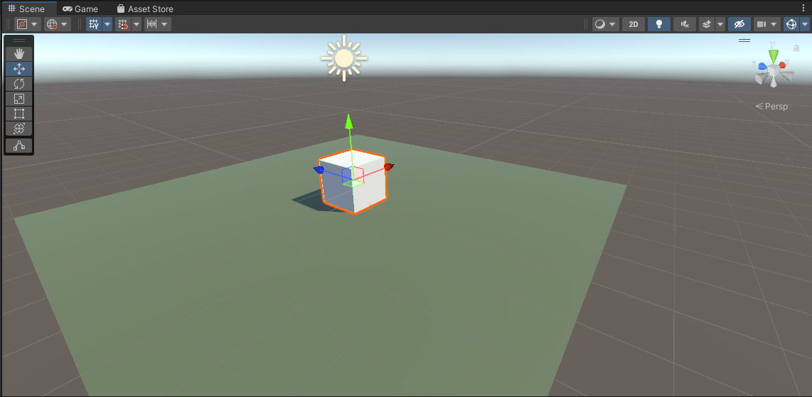
We then selected “Main Camera” in the scene and used the GameObject|Align with View menu command to set the camera to the same angle as the Scene View. Toggling between Scene View and Game View now show the exact same angle, at least until we move in the scene view again.
We create a Scripts folder and made a new C# script inside called “ShipController”. We dragged and dropped this script over the cube in the scene view to assign it.
The first thing we needed to do was to attach the ShipControls to the ShipController (similar names, but two different things). We made a new private property in ShipController to hold a reference to a ShipControls instance, added the Awake() function where we created a new ShipControls object and then used the OnEnable() and OnDisable() functions to enable and disable the ShipControls when the ShipController was itself enabled or disabled. This is what that code looks like:
using System.Collections;
using System.Collections.Generic;
using UnityEngine;

public class ShipController : MonoBehaviour
{
  private ShipControls _controls;

  private void Awake()
  {
    _controls = new ShipControls();
  }

  // Start is called before the first frame update
  void Start()
  {

  }

  private void OnEnable()
  {
    _controls.Enable();
  }

  private void OnDisable()
  {
    _controls.Disable();
  }
}
For movement we then just need to find out what the value of our input is at every frame and move appropriately. First though, we need some control over the speed we’re going to move. We add a new public property for MoveSpeed:
public class ShipController : MonoBehaviour
{
  public float MoveSpeed = 10.0f;
Now we can add code to Update(), the function that Unity calls every time that a frame is drawn, to move the cube around in response to player input.
If we have a speed and a time, we just need to multiply them together to see how far we’ve gone. This is a simple mathematical way of expressing it:
speed * time = distance
If, for example, I’m travelling 100kph and I drive for two hours then the distance I’ve gone is 200km.
100km/h * 2h = 200kmThe time between frames in Unity is stored in a special variable Time.deltaTime. This value for time is dependent on our framerate. As long as we use this value when we’re calculating distance moved in a single frame, the answer will be correct no matter if our computer is generating 20FPS or 200FPS.
Let’s see the final Update() function code:
  void Update()
  {
    Vector2 moveInput = _controls.Ship.Move.ReadValue<Vector2>();

    transform.position = transform.position +
                         new Vector3(moveInput.y * MoveSpeed * Time.deltaTime,
                                     0,
                                     -moveInput.x * MoveSpeed * Time.deltaTime);
  }
The first thing is that we ask for the value of the moveInput. This is defined as Vector2 value so it has an x and a y part (representing the horizontal and vertical axes respectively). The y component will be +1 when we’re pushing W (Up) and -1 when we’re pushing S (Down). Similarly the x component will be +1 when we’re pushing A (Left) and negative when we’re pushing D (Right).
We take transform.position, which controls the position of the cube and we set it to a new value which is it’s current position plus an new Vector3 which represents the change in position this frame. The x and z portions, which represent horizontal movement, are both calculated from the input. The y portion, representing vertical movement, is always zero. The other two are of the form:
distance = input * speed * timeDistance being speed multiplied by time we’ve seen, but what’s input doing in there? Well input is like a switch. When you’re not providing input, it’s zero. Anything multiplied by zero is zero, so distance must be zero when we’re not actively providing input. When you’ve providing input it’s either 1 or -1 which means we’ll move forward or backwards depending on what the input is.
Next week we’re going to make our ship a little more ship-like in proportion and make it bank when it goes sideways. We’ll also be creating a simple ship model in Blender.
All the code we’re made this year is on our GitHub. It can be found here. If you don’t have the latest version of our code before any session, use the green Code button on that page to get the “Download ZIP” option which will give you a full copy of all code we’ll be writing this year.
This week we finished off our feeding animals game and played another challenge round. This concludes our second project and we’ll be starting on a brand new project after Christmas.
There are two types of collider objects in Unity:
There is an “Is Trigger” check box on all collider components that allows us to change the type.
Standard colliders are used for physical interactions – like walls you can’t pass. Trigger colliders are used detect things being in the same space, but not physically interacting.
To detect collisions between two objects in Unity:
When Unity detects collisions, it sends messages to all components on the impacted GameObjects. We can choose to receive these messages by having the right functions in one (or more) of our components:
These are similar but differ in information they receive.
We selected each of the prefabs in our Prefabs folder and added a Box Collider to them. In the Game View we used the “Edit Bounding Volume” tool, as shown below, to adjust the Box Collider to make it a good fit.

To the Pizza Slice Prefab, we added a Rigid Body component and make sure to clear the option to “Use Gravity”.
We created a new script called DetectCollisions.cs and attached it to the animal prefabs. Editing this script we added the following function:
void OnTriggerEnter(Collider other)
{
  Destroy(gameObject);
}
Testing our code after this, we note that the animals disappear when they’re hit by a piece of pizza, but the pizza slices keep going. Once more change allows this code to remove the pizza slice as well:
void OnTriggerEnter(Collider other)
{
  Destroy(gameObject);
  Destroy(other.gameObject);
}
We implement the most basic possible “Game Over’ message by updating the Update() function in DestroyOutOfBounds.cs as follows:
    void Update()
    {
        if (transform.position.z > topBound)
        {
            Destroy(gameObject);
        }
        else if (transform.position.z < lowerBound)
        {
            Destroy(gameObject);
            Debug.Log("Game Over!");
        }
    }
Now, when an animal reaches the bottom of the screen, the message “Game Over” gets printed to the Console window Unity.
The code for this week’s project is on our GitHub, as always.
This week we finished our animation by texturing the plane to look like a tabletop and adding a background image of a desert island.
We also saw how to add an add-on to Blender, namely Lily Surface Scraper.
Here are the video instructions:
Here’s a link to the finished animation:
Here’s a link to the folder where we store all our files . You’ll find a new file in there called dubloon_wip3.blend, containing everything we did this week.
Hi folks.
This week we started looking at texturing. Texturing is the process of taking an image, which is flat, and mapping it onto a 3D object, which generally isn’t.
UV maps are just the plan that shows which part of the texture goes to which part of the 3D model.
Unwrapping is the process of taking the 3D surface of the model and laying it flat, like peeling an orange. This flattened version of the model, when placed over the texture becomes the UV map.

The animation above illustrates the process for a simple shape as if we really were unfolding the shape manually. In reality, we just tell Blender where the seams are (where it can cut the model’s surface) and the rest can happen automatically.
Here are the video instructions for this week:
The model file can be downloaded from here.
Next week, we actually paint the model and perhaps add a logo.
Hello Everyone,
This week we finished off our Paint Program from last week and did some more work with Pen Commands.

We didnt get to do all the code that is in the attached notes so if you want to give it a go yourself, that would be great. You can add a start and stop button and some variables.

Here are the full Pdf version of my notes from this weeks session. CDA-S8 Week 8-Pen Command.pdf
Hope to see you all this Saturday, we will be doing a great Maths Guessing Game!
Martha
Julie, Iseult, Eoin and Rauidhrí
Hi everybody,
 our drawing program. We made good use of costumes this week to make it look like we were dipping our paint brush in each of the different colours.
We also used a variable similarly to how we used in the Piano Game we made. We made it into a slider and then code select the Pen Size we wanted.
Here are the notes in PDF. CDA-S7-Week_08-Paint.PDF
Martha
This week we looked at making a painting program.
We started with three built in P5.js variables:
We put the call to background() in the setup() function because we didn’t want to clear the background every frame. After that, in the draw() function, we just needed to draw an circle at the mouse’s position every time the mouse button was pressed.
This gave us an very basic painting program in just a few lines of code!
Toolbar
We then looked at the idea of a toolbar to contain buttons for selecting colours and the size of the brush.
We first need to decide where it would be (the left side of the screen) and we created a variable toolbarSize to store the width of it.
In the draw() function we then added a check not to draw an circle if we were inside the toolbar area.
We then added a new function called mouseClicked(). This is a special function name (like setup() and draw()) that P5.js will call at the appropriate time. In this case its called when the mouse is clicked (button pressed down and the released).
Colour and Sizes
We created two arrays to store a list of colours and brush sizes at the top of our script:
let colours = ['black', 'white', 'red', 'blue', 'green'];
let sizes = [5, 10, 20, 40, 80, 160];
To draw the toolbar, we made a new function called drawToolbar() and put a call to it in our draw() function. In the new function, we looped over the colours array, drawing a new button, filled with the respective colour and then another loop over sizes drawing a square with a circle inside to represent the brush size. We needed to scale those circles to make them fit inside our buttons.
Detecting Selected Button
Since everything in our toolbar was toolbarSize high, to determine what had been clicked on, we just needed to divide mouseY by toolbarSize to get the index of the button that had been clicked on. We looked at that index, if it was less than the number of colours, we must have clicked on a colour. If greater, it had to be a size (or beyond the end).
Selected colours and selected sizes were stored in two variables called currentColour and currentSize respectively and used within the draw() function when creating our circles.
Featured Artwork
Mark suggested that people draw a portrait of me to test our new program and there were some brilliant renderedings. Three people were kind enough to share theirs with me so that I could put them here. I think they’re great!


Download
The files for this week can be found on our GitHub repository.
Hi everybody,
our drawing program. We made good use of costumes this week to make it look like we were dipping our paint brush in each of the different colours.
We also used a variable similarly to how we used in the Piano Game we made. We made it into a slider and then code select the Pen Size we wanted.
Here are the notes in PDF. CDA-S7-Week_08-Paint.PDF
Martha
