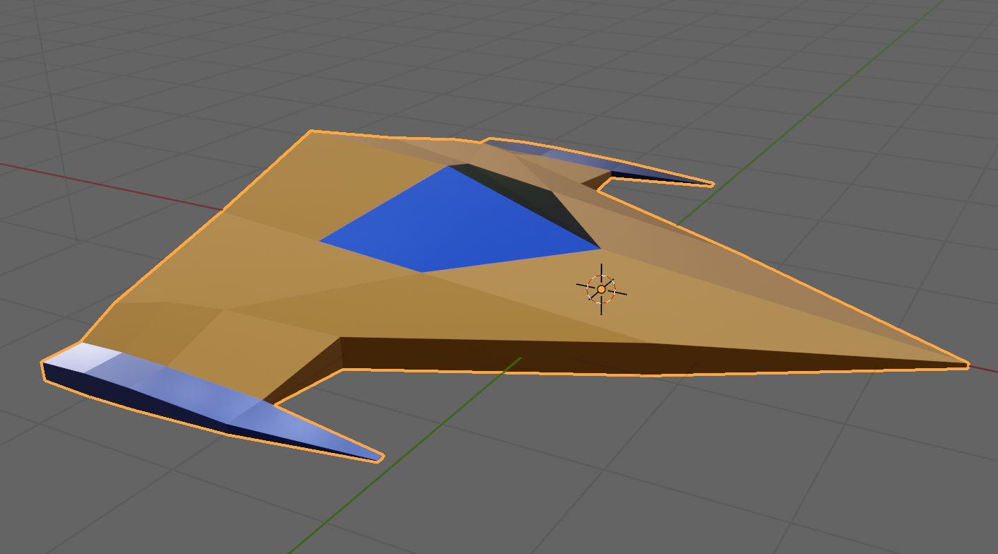
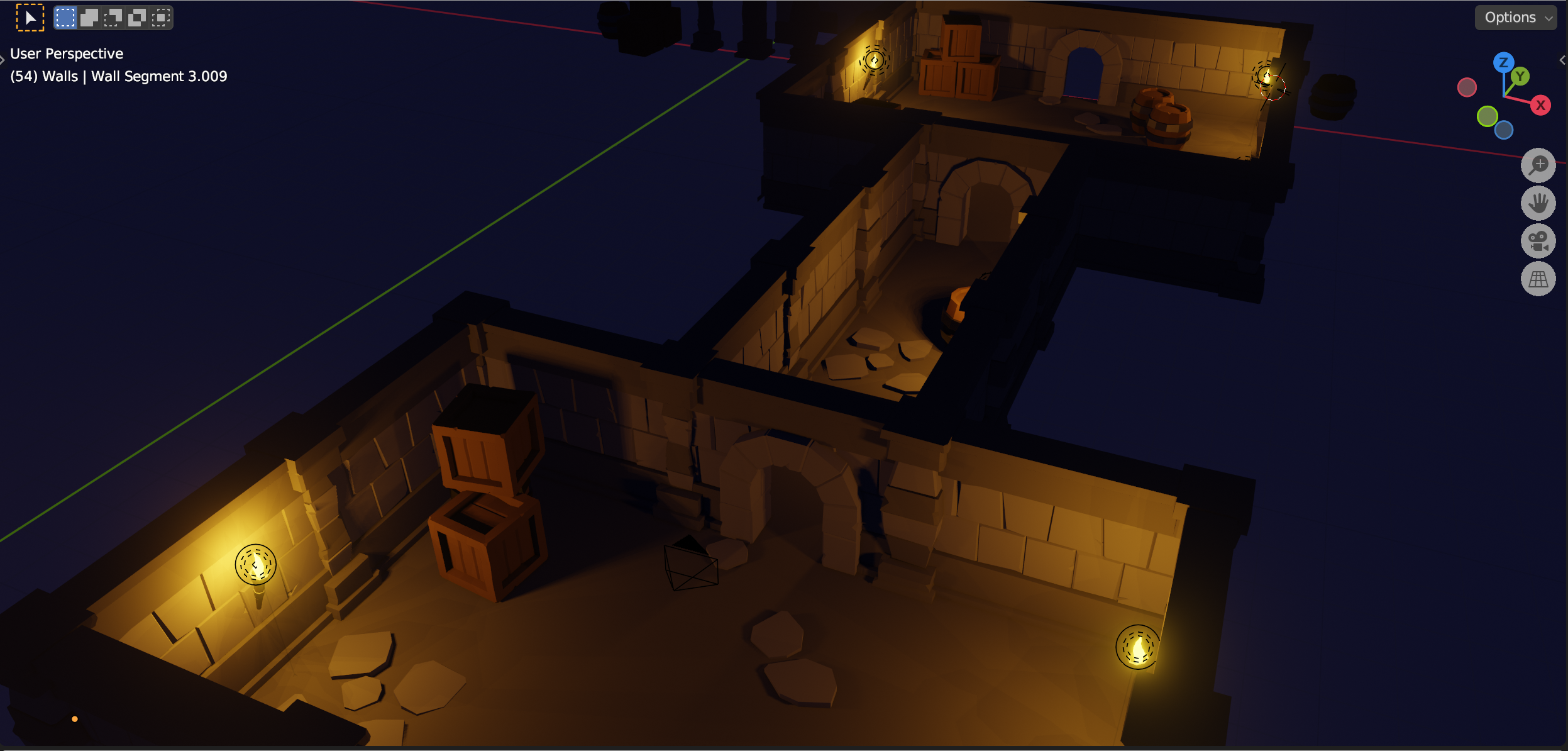
This week we took our Blender creations back into Unity. We started with the same file, ShipsAndEnv3.5,blend, which can be found here on our Teams site (for site members only).

Export from Blender
Blender offers extensive export options and we quickly ran through the list. The one we’re going to use is FBX. It’s a widely used format, well supported in lots of 3D software, with good material and animation support.

To export the file, we made sure all object were unhidden, and chose File|Export|FBX. We left all the options as-is except the “Apply Transforms” option, which we selected. This option has a warning next to it, as it doesn’t work with animations, but that doesn’t apply to us here.
The resulting FBX file was saved to the same folder as our BLEND file.
Import into Unity
To import the FBX file into Unity, we created a new folder called “Model” and dragged the FBX file from Windows Explorer/macOS Finder into it.
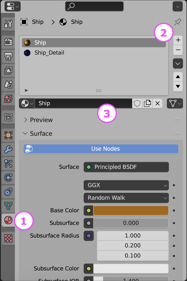
We decided to extract the materials from the file. This will allow us to change them in Unity. To do that we selected the FBX in the Model folder in Unity and in the Inspector window, went to the Material tab and chose “Extract Materials”. All the materials in the FBX were then extracted as Unity materials in the same folder as the FBX file.
Prefabs
We then wanted to break apart the combined FBX file into it’s separate parts. To do that we first created a blank scene and dropped the model from the “Model” folder into the Hierarchy window. We checked the Inspector window to make sure it was positioned at (0, 0, 0) and adjusted it if needs be.
Note that Unity showed the model coloured blue in the Hierarchy. This means it was treating it as a “Prefab”. A prefab in Unity is just a collection of GameObjects and components that are treated as a template. It’s easy to create copies of them at run-time.
We want prefabs of all the things in the FBX file, not the FBX model itself. To separate out the bits from the FBX model, we right-clicked on it in the hierarchy and chose Prefab|Break Apart Completely. Not much obviously changed except everything in the hierarchy turned black, indicating it was no longer a prefab, just normal objects.
We then created a new folder called “Prefabs” and dragged everything inside the FBX model (but not the FBX model itself) into it. That’s all you have to do to make something you already have in a Unity scene into a prefab, drag it into the Project window. Now we can create copies of all these objects at run-time very easily.
Adding our Ship to the Scene
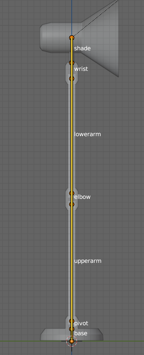
To add our ship to the scene, we dragged the Ship prefab from the Prefabs folder and dropped it onto the Player gameobject in the Hierarchy. The Ship model was then a child of the Player object. We needed to rotate the Ship by -90 around the Y axis to make it point in the correct direction. We also set the scale of teh Plater object to (1, 1, 1) and removed the Mesh Filter, Mesh Renderer and Box Collider components from Player, as these were no longer needed.
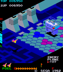
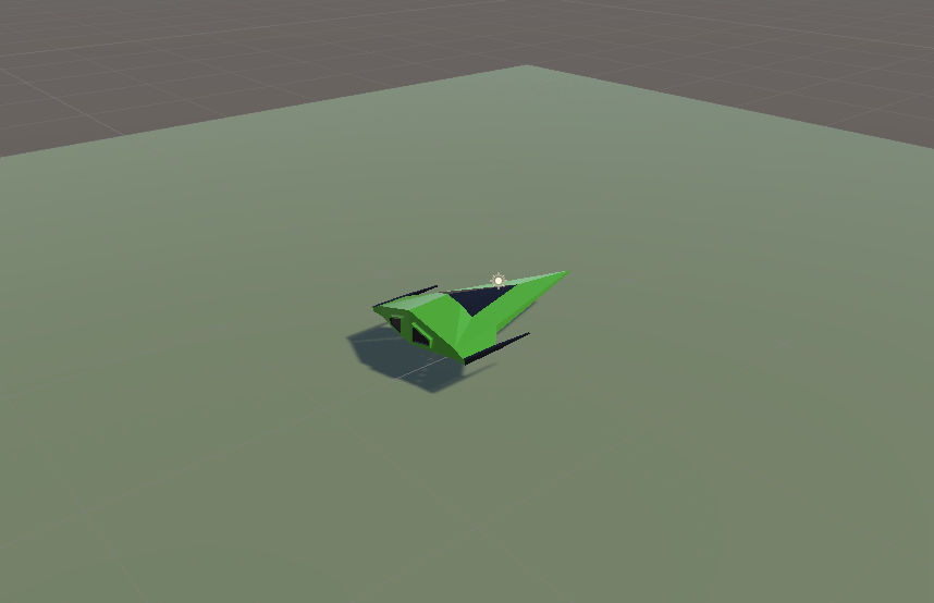
Our game looks better already with a ship model rather than a flying mattress!
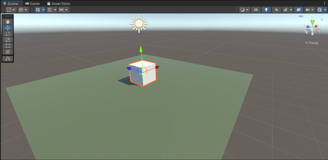
Some Test Code
We tested two simple components on a test cube added to the scene. One which created constant movement in a particular direction and the other which deletes the attached gameobject once we’ve traveled a set distance from where we started.
The first of these, ConstantMovement.cs looks like this:
using UnityEngine;

public class ConstantMovement : MonoBehaviour
{
  public Vector3 Direction = Vector3.forward;
  public float Speed = 10.0f;

  // Update is called once per frame
  void Update()
  {
    Vector3 offset = Direction.normalized * Speed * Time.deltaTime;
    transform.position = transform.position + offset;
  }
}
Two public variables define the direction and speed respectively. In Update() we calculate how to move this frame by multiplying the normalised version of the Direction (normalised meaning the length is set to 1) by the speed and Time.deltaTime (the time since the last frame). We then set a new value for the position by adding this offset to the previous position.
The second DestroyAfterDistance.cs looks like this:
using UnityEngine;

public class DestroyAfterDistance : MonoBehaviour
{
  public float Distance = 10.0f;

  private Vector3 _initPos;

  // Start is called before the first frame update
  void Start()
  {
    _initPos = transform.position;
  }

  // Update is called once per frame
  void Update()
  {
    Vector3 offset = _initPos - transform.position;
    float offsetDist = offset.magnitude;

    if (offsetDist >= Distance)
    {
      Destroy(gameObject);
    }
  }
}
It just has once public variable, the distance the GameObject is allowed to travel. It also has one private variable, set in Start(), which stores the initial position.
In Update() we check how far we’ve travelled by getting the vector difference between the start position and our current position and then getting it’s magnitude (aka length). This tells us how far we have moved. if this distance is greater than the the specified Distance, we call Destroy(gameObject) thereby destroying the GameObject this component is attached to.
Getting the Code
All the code we’re made this year is on our GitHub. It can be found here. If you don’t have the latest version of our code before any session, use the green Code button on that page to get the “Download ZIP” option which will give you a full copy of all code we’ll be writing this year.