Creators – Week 4

This week we took a pre-made scene with some problems and set out to fix them.

The first two issues were that the plane was flying backwards and at great speed. The initial challenge was to identify what was making the plane move. Looking at the plane, called Player in the scene, in the inspector, we could see it has a script component called Player Controller X added to it.

Double-clicking on the name of the script file (PlayerControllerX.cs) in the inspector allows us to open it. The code for moving the plane is in the Update() method:

        // get the user's vertical input
        verticalInput = Input.GetAxis("Vertical");

        // move the plane forward at a constant rate
        transform.Translate(Vector3.back * speed);

        // tilt the plane up/down based on up/down arrow keys
        transform.Rotate(Vector3.right * rotationSpeed * Time.deltaTime);

We need to concentrate on the line that starts transform.Translate(…). The comment above it says “move the plane forward”, but the line itself is specifying Vector3.back as the direction of movement. Changing this to Vector3.forward makes it move in the right direction. The plane is still much too fast though. This line is asking the plane to move the distance specified by the speed parameter (by default 15m) every frame. What we need to do is to multiply here by Time.deltaTime, the amount of time since the last frame, to convert this movement into 15m per second, not per frame. Here’s the corrected line:

        // move the plane forward at a constant rate
        transform.Translate(Vector3.forward * Time.deltaTime * speed);

The next problem is that the plane turns on its own. In fact, although we’re gathering the value of the “Vertical” input axis in the code, pressing the arrow keys does nothing. We can identify the line of code that’s making the plane turn:

        // tilt the plane up/down based on up/down arrow keys
        transform.Rotate(Vector3.right * rotationSpeed * Time.deltaTime);

This is asking the plane to rotate around Vector3.right (horizontally through the plane) by the number of degrees specified by the property rotationSpeed (with a default value of 100) every second. The multiplication of Time.deltaTIme is what makes it “every second” and not “every frame”, as before. So the plane is turning 100degrees every second, making it do a full loop approximately every three and a half second.

Nowhere here are the user inputs taken into account. How can we use them? Remember that the “Vertical” input axis in Unity works like this:

Input Option 1Input Option 2Axis Value
WUp-arrow+1
<No key pressed><No key pressed>0
SDown-arrow-1

We’re gathering this axis value into a property called verticalInput already, we just need to use it. When multiplied in, it works like a switch. If its off (having the value zero) then no rotation happens. If it’s one or minus one, rotation happens in either a positive or negative direction:

        // tilt the plane up/down based on up/down arrow keys
        transform.Rotate(Vector3.right * rotationSpeed * Time.deltaTime * verticalInput);

Now the plane flys correctly and responds to user input, but the it flies directly into the camera and then can’t be seen any more. First we need to grab the camera and move it to the side of the plane, rotating it around to point at the plane. This is better, but it still doesn’t move. The plane quickly flys beyond the area the camera can see. If we look at the camera in the inspector, we can see that it already has a script called Follow Player X on it:

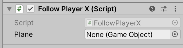
It has a property called Plane, but nothing’s assigned there. We can set this by dragging and dropping the plane from the hierarchy, or by clicking the small circle icon on the right above and picking the “Player” object from the pop-up list. Running and testing this shows that the camera now follows the plane, but it’s right on top of the plane. It needs to be some distance away. Examining the FollowPlayerX.cs script we see at the top there’s a private property called offset:

    private Vector3 offset;

that is used in the Update() method already:

    transform.position = plane.transform.position + offset;

We just have to give it a value. The easiest way is to change private to public and then specify a value for the offset in the inspector.

The final challenge is to turn the plane’s propellor. Looking in the inspector, we can see this is its own object, a child of the “Player” object:

To make it spin, we can make a simple new script called SpinPropellor.cs and attach it to the propeller. This code works well:

using System.Collections;
using System.Collections.Generic;
using UnityEngine;

public class SpinPropellor : MonoBehaviour
{
    public float spinSpeed;

    // Start is called before the first frame update
    void Start()
    {
        
    }

    // Update is called once per frame
    void Update()
    {
        transform.Rotate(Vector3.forward * Time.deltaTime * spinSpeed);
    }
}

This is very similar to what we’ve done before, but the axis of rotation is the Vector3.forward here to make the propellor spin in the expected way. I found a value of 1000 or more was good for spinSpeed.

Note that although we’re moving the propellor ourselves, or at least rotating it, that doesn’t interfere with the fact that it’s moving with the plane, because it’s a child object.

Code for this Week

Updated code is on our GitHub repo: https://github.com/coderdojoathenry/Creators-2022 The problems with projects not loading correctly when downloaded has been corrected.

Creators – Week 3

This week we continued our project from last week, looked at three main topics:

  1. Frame rate independence
  2. Creating our own properties on our components
  3. The Input Manager and getting and using user input

Frame Rate Independence

We covered how to make our actions independent of frame-rate. The code:

transform.Translate(Vector3.forward, 20.0f);

moves the object 20m in every frame. As we know, frame-rate isn’t generally consistent between machines. On my powerful laptop, I was getting up to 1400 frames per second at fastest. Most ninjas were getting a few hundred frames per second on theirs.

On the other hand, the code here:

transform.Translate(Vector3.forward, Time.deltaTime * 20.0f);

moves the object at a consistent 20m per second on everyone’s machine. The magic is that Time.deltaTime variable. It is the time, in seconds, since the last frame was drawn. The faster the frame-rate, the smaller this number gets and the result is a consistent 20m per second movement.

Creating Properties on our Components

We can add properties, variables where we can hold and values that we can then use, to our classes by typing a single line into our class definition:

class MyBehaviour : MonoBehaviour
{
  // The new property
  public float myProperty = 1.0f;  

  void Start()
  {
  }
  void Update()
  {
  }
}

Looking at the bits of the line in turn:

  • public – The access modifier. Can be private, internal (which we won’t use) or public. If it’s public we can see it in the inspector, and from other classes. If private we can only see and use it within the class itself.
  • float – The type of value we are storing. A float is a number with a decimal point. An int (short for integer) is a number without one. We might use an int for counting things, but we use floats for real world measures like speeds and positions, etc.
  • myProperty – the name of the variable
  • = 1.0f – Assigning a default value to this property. This portion is optional. the ‘f’ after the number is just a hint to the computer that this is a float value.
  • ; – The standard semicolon to end the line of code.

The Input Manager and Using User Input

Unity’s Input Manager contains the definition of input “Axes”. These can contain many ways of doing the same thing.

The default definition of the “Horizontal” axis means it can be triggered by the keys A and D, or the Left and Right arrow keys or by the joysticks or d-pad on a game controller.

This means input is “abstracted”; we can write our script to respond to input, without worrying how that input is generated.

To get the value of input on an access we need to use code like this:

forwardInput = Input.GetAxis("Vertical");

Here we’re getting the value of the axis called “Vertical” and storing it in a variables called forwardInput.

The value of the vertical axis goes between -1 and 1. Minus one means fully down, zero means no input and one means fully up. Because of this range, we can use this value like a switch, multiply it with other numbers. When there’s no input, it’s zero which will zero out the expression it’s part of.

Here’s the fully updated code for our PlayerController.cs:

using System.Collections;
using System.Collections.Generic;
using UnityEngine;

public class PlayerController : MonoBehaviour
{
    public float speed = 20.0f;
    public float turnSpeed = 50.0f;
    private float horizontalInput;
    private float forwardInput;

    // Start is called before the first frame update
    void Start()
    {
        
    }

    // Update is called once per frame
    void Update()
    {
        // Get the player input
        horizontalInput = Input.GetAxis("Horizontal");
        forwardInput = Input.GetAxis("Vertical");

        //  Move our vehicle forward
        transform.Translate(Vector3.forward * Time.deltaTime *
                            speed * forwardInput);

        // Rotate our vehicle 
        transform.Rotate(Vector3.up, turnSpeed * Time.deltaTime *
                         horizontalInput);
    }
}

Code for this Week

Updated code is on our GitHub repo: https://github.com/coderdojoathenry/Creators-2022

Creators – Week 2

Hi folks, this week we started our first project. We have a truck that can drive down a road, avoiding obstacles, or maybe not!

We created a new project in Unity, using the default 3D Core template, and called it Prototype 1.

We then downloaded and imported the assetpack from here: [Creators Teams Channel]

The asset pack already included an existing scene, which had a simple environment already. We them dragged in a vehicle and obstacle from the imported assets. Imported assets aren’t just models; they can contain Unity obstacles, such as colliders, already.

To make the truck move, we made a new C# script called PlayerController. The new C# files Unity creates always look the same (apart from the name of the Class, which matches the new file name):

We added the following code to the Update() method to change the transform of the vehicle:

    // Update is called once per frame
    void Update()
    {
        //  Move our vehicle forward
        transform.Translate(0, 0, 1);
    }

The Unity scripting documentation can be found:

https://docs.unity3d.com/ScriptReference/index.html

and the specific page for the Transform component is:

https://docs.unity3d.com/ScriptReference/Transform.html.

This method on the Transform component that we’re calling, Translate() has several forms. The one we’re using here expects us to provide X, Y, Z values. What we’re saying we want to happen is “Change the transform by moving it 1m in Z every frame.

When we run, the car moves very fast off the end of the road. That’s because we’re running at many frames a second. It’s too fast. Next week, we’ll look at making this frame rate independent and controlling the speed.

Finally, I’ve created a GitHub repo for our projects this year. Up-to-date versions of our projects will always be available here after our sessions: https://github.com/coderdojoathenry/Creators-2022

Creators 2022/2023 – Resources

Here are links to a few resources we’re going to need this year:

You are going to need an email address so you can register for Unity and Microsoft.

Unity:

https://unity3d.com/get-unity/download

Install Unity Hub. Create a Personal account. Install the latest standard version of Unity version 2021.3. Include Visual Studio.

Teams: https://teams.microsoft.com/l/channel/19%3a87100ae29304432397b969f52a3bcc15%40thread.tacv2/2022%2520Projects?groupId=cedb60b0-c5f6-4f2e-a3b7-e4a14d09d9c5&tenantId=adf6361d-b4dc-42d2-b27a-9d409b9757c8

Click on the link. Log-in to your Microsoft account, or create one if necessary.

Modellers – Weeks 5 & 6

We completed our dioramas with materials and lights and rendered the final images. Some people chose their own colours and some used a palette generator (see: https://coolors.co/bf4e30-c6ccb2-093824-e5eafa-78fecf) to choose a complimentary set of colours to provide a harmonious look for our scene.

We used the Cycles rendered and turned on the denoising options, which automatically remove any graininess from the resulting render, to give us a high-quality output in a reasonable timeframe.

We then built a simple model of an articulated desk lamp. Built as a single mesh and composed of simple primitive objects, all starting as cylinders or cubes, we developed it initially in a completely linear vertical configuration.

We then created vertex groups for each distinct portion of the lamp and assigned those parts of the lamp to those vertex groups. From the bottom up, these groups were:

  • base
  • pivot
  • upperarm
  • elbow
  • lowerarm
  • wrist
  • shade

We then added a spot light to represent the lamp’s bulb.

Next we generated a new armature. In edit mode, we scaled the initial bone until it was just the size of the base vertically and called it base, the name matching that of the vertex group in the lamp model. We then extruded the tip of this bone vertically to the centre of the first hinge pin in the model. This bone was named pivot again matching the name of the corresponding vertex group. We repeated this until there was a bone, named for the corresponding vertex group, across each section of the model.

We then returned to edit mode and, selecting first the armature and then shift-selecting the model, we used Parent | Armature Deform from the object menu to associated them together. The mesh became a child of the armature. Selecting the armature and changing to Pose mode, we were able to see how rotating the bones allowed us to move the model in a simple and non-destructive way.

We then wanted to move the light with the armature as well, as it currently remained in space where we’d located it originally. To do this we selected the spotlight object and added an object constraint tying it to the the shade bone in the armature, as shown below. This moved the light, so we needed to reposition and rotate it again to get it in the correct location.

The final step was adding an inverse kinematic control bone into the rig. Moving an inverse kinematic (IK) bone automatically moves all connected bones to try to follow the movement of the control bone. In the armature, in edit mode, we added a single bone and located it near the rim of the lamp shade. We called it “control” and, selecting it and then the shade bone, used Armature | Parent | Make | Keep Offset to join them.

We then switched to pose mode. Once in pose mode, we could add an IK constraint to the control bone as shown below. All defaults here are fine in this case.

Then we saw that moving this bone in Pose mode caused the rest of the lamp to follow, however some parts of the lamp were moving in ways we didn’t want. The final step was to place some IK limits on certain bones in the Bone Properties Panel. For the base we locked x, y and z because we didn’t want it to rotate at all:

For pivot and shade, we locked then in x and z, this will allow them to turn around their own axis but not bend over. For all the others we locked them in y and z allowing them to bend over corresponding to the way they were pinned in the model.

Files for these final models can be found on our Sharepoint site.

Modellers – Week 4

This week we continued with adding more props to our diorama. Of these the gaming chair was the most complex.

To make the five-footed design of chair base we started with a cylinder with twice as many sides and then, after placing an edge loop near the bottom, extruded every second face to form the feet. We then extruded these feet ends a second time and extruded a few more times to form a roughly spherical shape to represent coasters.

The chair seat was just a cube, scaled to the appropriate proportions and then the front and back faces extruded and scaled slightly to round out the shape. We duplicated the seat and moved and rotated it to form the chair back as well.

The arms were created by first duplicating the faces on the left and right of the chair seat, scaling them vertically and moving them up into position. The reason for doing this with copied faces was because it ensured they were perfectly aligned to the rest of the chair. These faces where then extruded with the “Extrude along face normals” command [Keystroke: Alt-E] to give them width. Finally we extruded the back faces of these two arms, down to the bottom of the chair back, by selecting them, going to a side view and using the Ctrl-Right Click command.

We also added a few more simple props. These were all based on cubes, scaled to size and shaped using inset, extrude and edge loops.

This is the final room, from a geometry perspective. We still need to give materials to the objects, light the scene and render a final image.

Files for this weeks work-in-progress model can be found on our Sharepoint site.

Modellers – Week 3

After mostly doing a review of the basic functions of Blender in Weeks 1 and 2, we started our first real project this week; a diorama of a room populated with low-poly props, rended by an orthographic camera from an isometric perspective.

A screenshot of Blender showing the diorama as a work-in-progress.

Most of the time we use perspective cameras. With perspective cameras, like in the real world, things appear smaller the further away they are. An orthographic camera does not have that effect; things stay the same size no matter how far away they are. In the image above the right-hand pane shows the view from the orthographic camera while the left-land shows a standard perspective view. You can see how the cube shape is emphasised using the orthographic camera; it’s a stylistic choice.

We are also using an isometric view point. This is one where the camera is positioned approximately the same distance along each axis and looking back towards the origin. It’s a style of presentation that has been made popular in many games down the ages and again is a stylistic choice. Search Google Images for “game isometric” to see examples.

We learned how to split the Blender view by dragging from the bottom left corner with the mouse. This split view allows us to maintain the camera view on one screen while we actively edit on the other.

Blender Viewport Shading Options

We set some options for Viewport Shading to help understand the model as we build it. These are shown above. Shadow and cavity help emphasise edges and geometry. Switching “Color” to “Random” helps us quickly visually distinguish distinct object while we still don’t have separate materials assigned to them.

All the objects were built with the following techniques:

  1. Loop-cuts
  2. Edge and face loop selection, movement and scaling
  3. Inset
  4. Face duplication and separation (to create new objects)
  5. Bridge edge-loops

The first three of these are very familiar, but we can talk about the other two. A few places, such as around the hole in the wall cut for the window, we had a set of existing faces that could be repurposed to form the basis of another object, in that case the window itself. Duplication of faces is accomplished with the keystroke shift-d, followed by enter to confirm. The duplicates, already selected, can then be separated by pressing p and choosing “Selection”.

Bridging edge loops we used in two ways. In the first, we had faces on opposite sides of a box. Selecting them both and choosing “Bridge Edge Loops” from the “Edge” menu causes a hole to be punched out between these faces,. The original faces are removed and the internal edges of the new hole are filled in.

The second way we used it was to join two faces opposing each other across a gap. In this case the faces are again themselves removed and a solid connection between the faces original locations is created across the gap.

Next we are going to continue to model props within the room and, time permitting, assign materials and render a final image.

Files for this weeks work-in-progress model can be found on our Sharepoint site.