Hi folks, here are some photos from our end-of-year party today and a photo of some ninjas, some mentors and some Tesco members of staff at Tesco Athenry marking the end of our Community Fund collection period. Thanks to Tesco Ireland and to everyone who dropped a blue token in the box for us!
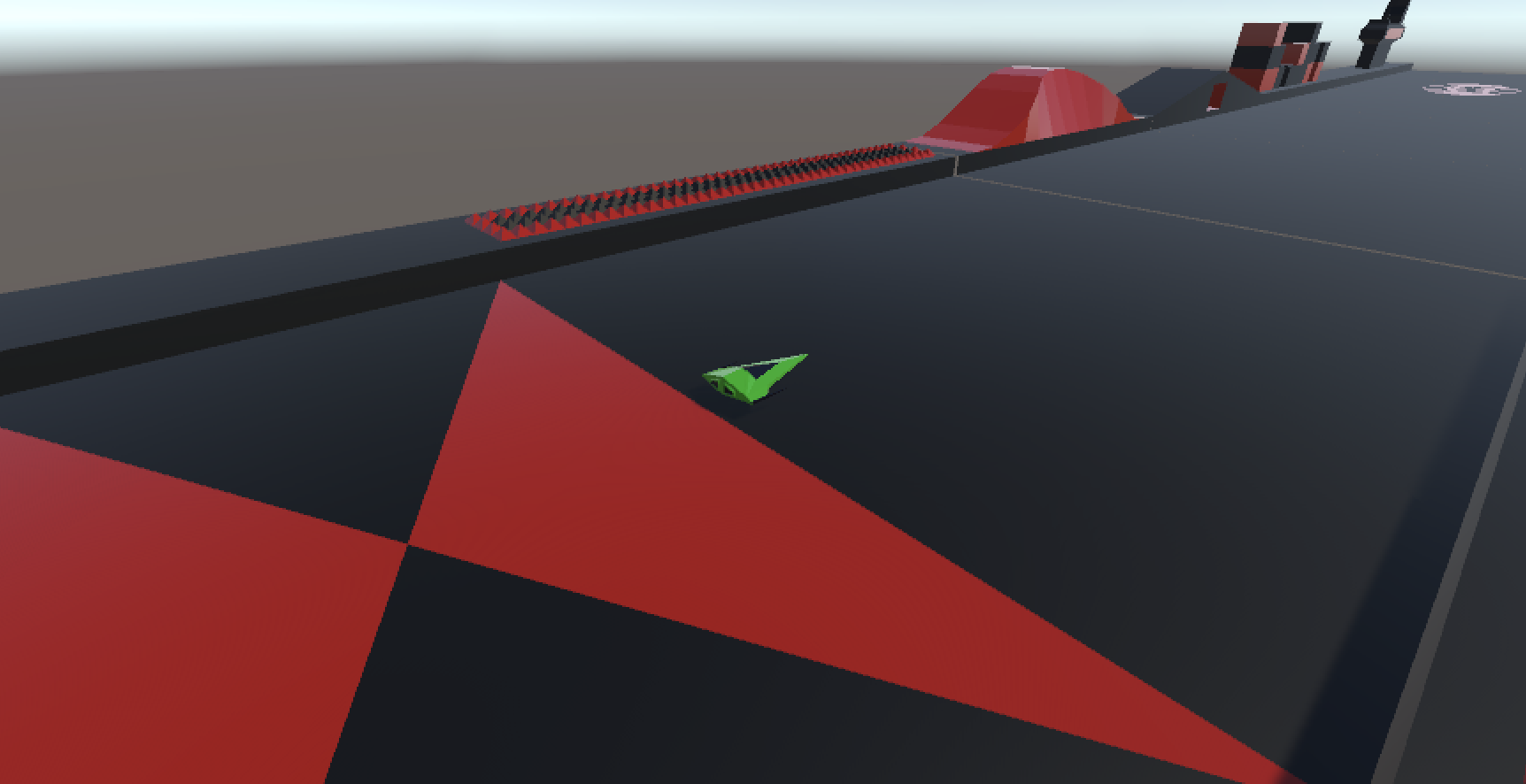
Hi folks, we finished as much of Speedy Spaceship as we could this week. I took it and added a few finishing touches:
My high score has been 71k. See if you can do better!
The code is available from our GitHub, as always. I’m sure the game could be made even more fun with some clever tweaking of speeds and rates. If you give it a go, be sure to let me know.
Thanks for a fun year and I hope we’ll see some of you next year.
Made our missiles explode when they hit an obstacle
Changed our lighting, environment materials and skybox
Made our ship go into a special invulnerable mode just after hitting an object
A lot of progress! Let’s get into it.
Audio Files
We sourced three audio files:
A musical track to play as our game theme
The sound of a missile being fired
The sound of an explosion
There are lots of places to find royalty free music and sound online. Freesound.org is one. We placed them in an folder in the project called Audio.
Game Audio
For the game audio, we added an empty game object at the top of our scene called [Audio] and added an AudioSource component to it, setting the clip to our game theme and making sure that Play on Awake and Loop were both set to true.
Shooting
To have the sound of a missile shooting we added an AudioSource to our Player object and set the clip to our shooting sound and set both Play on Awake and Loop to false. In our ShipController.cs we added a new private property:
private AudioSource _audioSource;
which we then assigned automatically in the Start() function:
GetComponent<T>() looks for a component of the requested type (here AudioSource) on the current GameObject and returns it.
Finally, in Shoot(), we added the following:
    if (_audioSource != null)
      _audioSource.Play();
Destroy On Contact
We wrote a script to destroy something if it hits something else. This is it:
using UnityEngine;

public class DestroyOnContact : MonoBehaviour
{
  public GameObject DestroyPrefab;

  private void OnTriggerEnter(Collider other)
  {
    if (DestroyPrefab != null)
    {
      Instantiate(DestroyPrefab, transform.position,
                                 transform.rotation,
                                 other.transform);
    }

    Destroy(gameObject);
  }
}
The code simply calls Destroy(gameObject) when contact is detected. It also has an optional GameObject called DestroyPrefab. If this is supplied, it will be created at this items current position and rotation, but it will be parented to the thing that was hit, meaning if that thing is moving, then the DestroyPrefab will continue to move with it.
Destroy After Seconds
Another simple script that destroys the attached GameObject after a given number of seconds.
using UnityEngine;

public class DestroyAfterSeconds : MonoBehaviour
{
  public float TimeToLive = 1.0f;

  // Start is called before the first frame update
  void Start()
  {
    Destroy(gameObject, TimeToLive);
  }
}
The Destroy() function already has an optional delay argument, so this is very easy to write.
Explosion Prefab
We created our Explosion prefab last week. It was just a quad with a script to keep it always pointing directly at the camera.
To that we added a DestroyAfterSeconds component with a Time To Live of one second and an AudioSource component where the clip was set to our explosion sound, Play on Awake was set to true and Loop was set to false.
Updates to the Missile Component
The original missile was very small, so we scaled the model part to (3, 3, 3). We then added a BoxCollider, a kinematic RigidBody and a DestroyOnContact component. For the DestroyOnContact component, we set theDestroy Prefab property to our Explosion prefab.
Skybox, Lighting and Colours
We imported a image of stars into our Textures folder. In the Material folder we created a new Material called StarsSkybox. We changed the Shader to Skybox/Panoramic and assigned our stars image to the Spherical (HDR) slot. We also changed Image Type to 180 degrees.
To assign this skybox to our scene, we used the Window|Rendering|Lighting menu to open the Lighting dialog and set the skybox material at the top of the Environment tab.
We changed the colours of our Environment_main and Environment_details0 materials to #BF4C00 and #EC9100 respectively. We then applied these materials to all our Obstacle prefabs as well.
Finally we increased the intensity of our Directional Light object from 1 to 1.5.
Making Ship Go Invulnerable After Hitting an Object
We want our ship to go into a special invulnerable mode after hitting an obstacle. Specifically we want it to:
Change appearance to be partally transparent
Still be able to move, but not be able to shoot
Be invulnerable to collisions
Return to normal after two seconds
To achieve this we had to first duplicate the Ship_body and Ship_details materials as Ship_body_transp and Ship_details_transp respectively. On both of these new materials we set the Rendering Mode to Transparent and edited the Albedo to change the Alpha (transparency) value from 255 (solid) to 127 (half transparent).
We then created a duplicate of the Ship model under the Player game object and called it Ship Transparent, we changed it’s materials to the transparent ones and set it inactive by default.
In ShipController.cs we added several new public and private properties:
  public GameObject StandardShip;
  public GameObject InvulnerableShip;

  private bool _shootingDisabled = false;

  private Collider _collider;
We added code in Start() to set _collider:
_collider = GetComponent<Collider>();
In Update() we added code to check if we’re allowed to shoot:
private void SetMode(bool isInvulnerable)
  {
    // Set the ship models on/off
    StandardShip.SetActive(!isInvulnerable);
    InvulnerableShip.SetActive(isInvulnerable);

    // Set shooting on/off
    _shootingDisabled = isInvulnerable;

    // Set contact on/off
    _collider.enabled = !isInvulnerable;
  }

  public void SetModeNormal()
  {
    SetMode(false);
  }

  public void SetModeInvulnerable()
  {
    SetMode(true);

    Invoke("SetModeNormal", 2.0f);
  }
The function SetMode() does all the work of switching modes from normal to invulnerable. The two functions SetModeNormal() and SetModeInvulnerable() just call it except that SetModeInvulnerable() also puts in delayed call to SetModeNormal() after two seconds. This means after we go invulnerable, we’ll automatically be vulnerable again after two seconds.
Finally, we just needed to call this in OnTriggerEnter():
All the code we’re made this year is on our GitHub. It can be found here. If you don’t have the latest version of our code before any session, use the green Code button on that page to get the “Download ZIP” option which will give you a full copy of all code we’ll be writing this year.
This week we looked at adding obstacles to our game and detecting collisions.
Obstacles
The obstacles were created in Blender and provided as an FBX file. To process them we:
Imported the FBX
Added it to the scene temporarly
Used the Prefab | Unpack context menu option to allow editing of the individual items
Edit each obstacle in turn, adding one or more Box Colliders to cover each part of the shape
Made sure each Box Collider was marked as “Is Trigger”
Dragged each one individually into the Prefabs folder to make it a prefab
Deleted the model from the scene
Collisions in Unity
Generally speaking, Unity tracks collisions between objects as long as:
One has a RigidBody component attached
Both have collider components attached
Unity draws a distinction between RigidBody components depending on the setting of “Is Kinematic”. If “Is Kinematic” is false, Unity takes responsibility for moving the object according to physics rules. If “Is Kinematic” is true, we’re responsible for moving the object, but Unity will still track if for collisions, etc. The latter is appropriate for our game.
When Unity detects collision it looks for functions OnTriggerEnter() or OnCollisionEnter() to call, depending on whether the RigidBody is kinematic or not. Ours isn’t so we’ll be implementing OnTriggerEnter() when it’s time to do so.
Generating Obstacles
We added two new public properties to EnvController.cs, one to determine how likely that a piece of environment contains an obstacle and another to hold the prefabs for the obstacles:
  public float ChanceOfObstacle = 0.2f;
  public GameObject[] ObstaclePrefabs;
We then added a new function GenerateObstacles() to EnvController.cs:
  private void CreateObstacle(Vector3 position, Transform transform)
  {
    // Pick a random prefab
    int numPrefabs = ObstaclePrefabs.Length;
    GameObject prefab = ObstaclePrefabs[Random.Range(0, numPrefabs)];

    // Create an instance of it
    Quaternion rotation = Quaternion.Euler(0, -90, 0);
    GameObject go = Instantiate(prefab, position,
                                rotation, transform);

  }
and called it from just before the last line of CreatePrefab():
    // Create obstacle?
    if (Random.value <= ChanceOfObstacle)
    {
      // Create an obstacle as a child of this piece of env
      CreateObstacle(position, go.transform);
    }
Preventing Obstacles at Start
We don’t want obstacles at the start because they can lie on top of our ship. Adding a second argument to CreatePrefabs() allows us to control this:
Because this argument has a default value (= true) and is at the end of the argument list, this makes it optional. If we don’t use it, it’s assumed that we want obstacles.
We can check this value were we create obstacles:
    // Create obstacle?
    if (createObstacles && Random.value <= ChanceOfObstacle)
    {
      // Create an obstacle as a child of this piece of env
      CreateObstacle(position, go.transform);
    }
The double-ampersand (&&) means “and”. Both things have to be true or no obstacles are created.
Finally we modify Preload() so that obstacles are not created when it’s generating the first few environment pieces:
  private void Preload()
  {
    for (int i = 0; i < Count; i++)
    {
      Vector3 pos = Vector3.right * i * Spacing;
      _lastGo = CreatePrefab(pos, false);
    }
  }
Setting Up the Player
To set up the player for collisions, we need to:
Add kinematic RigidBody
Add and size a BoxCollider
Add OnTriggerEnter() to ShipController.cs
With our simple OnTrigger() we can see when collisions are being detected:
  private void OnTriggerEnter(Collider other)
  {
    Debug.Log("I hit something");
  }
Getting the Code
All the code we’re made this year is on our GitHub. It can be found here. If you don’t have the latest version of our code before any session, use the green Code button on that page to get the “Download ZIP” option which will give you a full copy of all code we’ll be writing this year.
Please note that there was no Week 14 session as it had to be cancelled owing to bad weather.
Closing The Gap
When we finished our last session, our EnvController was creating random pieces of environment continuously and scrolling them under the ship. It looked good, but there were gaps between the environment pieces, getting larger the higher we set the environment speed.
Why was this gap happening? Well it’s easy to understand if you look at it this way: if something is moving and you shout stop at a random time, what are the chances that it’s moved some exact distance? Almost no chance of that at all. This is what the current code is doing and why, the faster it’s moving, the larger the gaps get.
The first thing we can do to make this easier is to check more often if the blocks have moved far enough to create a new one. By changing Update() to FixedUpdate() this helps because while Update() is called every frame, FixedUpdate() is called much more often and on a regular timer, independent of frame rate. It’s normally used for physics calculations.
The second thing we can do is to not create our new block at _spawnPoint but to work out the proper position to create it so it’s exactly 100m from the previous one. This is what that code looks like:
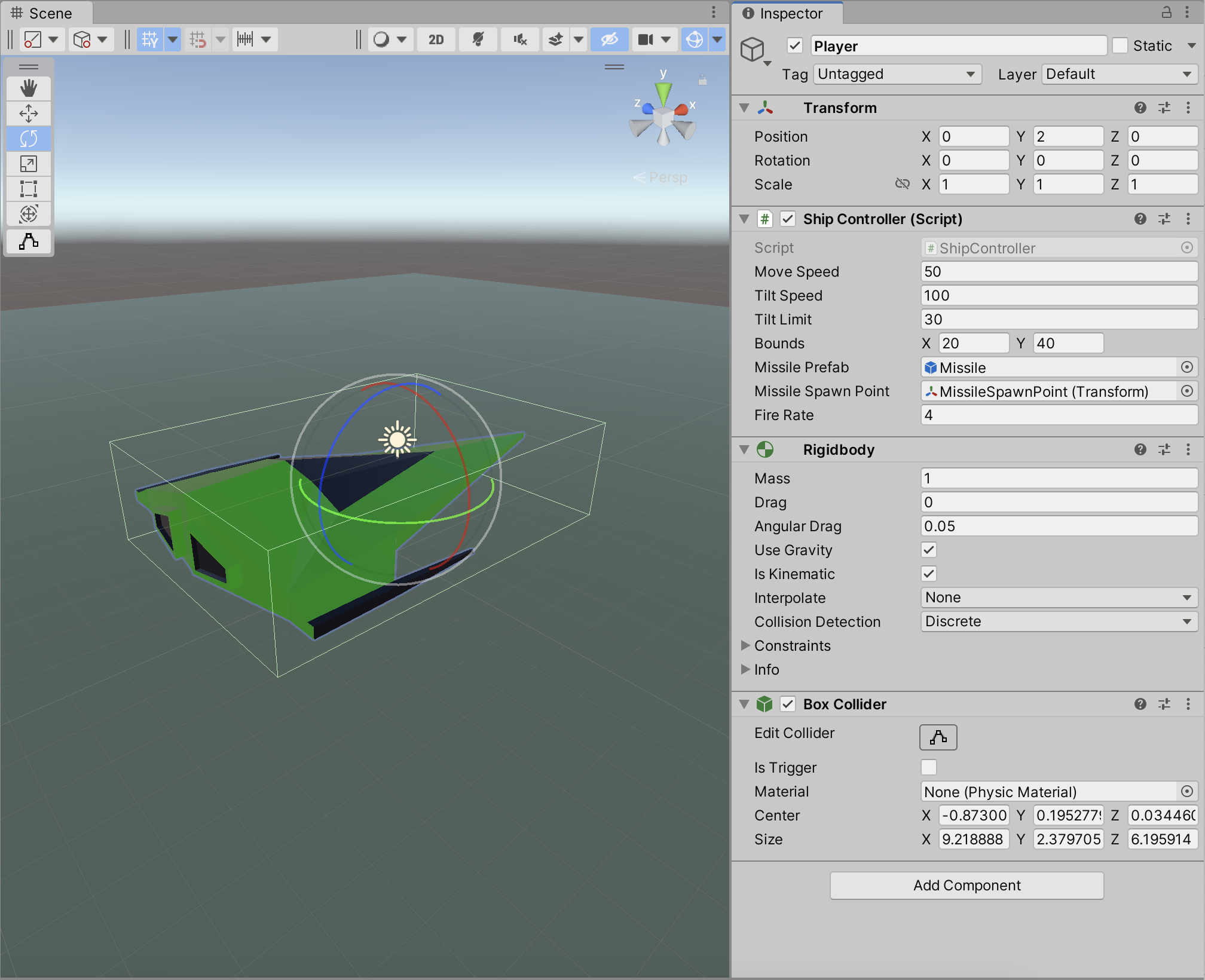
I thought we’d done this ages ago, but we never implemented bounds checking for our ShipController. It’s only supposed to be able to move within a fixed area. To achieve this we added a new property to ShipController of type Vector2d called Bounds. We are going to use the x part of this property to store how far we want to allow the ship to move forward and backwards and we’re going to use the y part to store how much we want to allow the ship to move side-to-side. In testing we found good values for this were (20, 40). Here’s the change to the ShipController.Update() function:
    Vector3 newPos = transform.position +
                         new Vector3(moveInput.y * MoveSpeed * Time.deltaTime,
                                     0,
                                     -moveInput.x * MoveSpeed * Time.deltaTime);
    if (newPos.x > Bounds.x)
      newPos = new Vector3(Bounds.x, newPos.y, newPos.z);

    if (newPos.x < -Bounds.x)
      newPos = new Vector3(-Bounds.x, newPos.y, newPos.z);

    if (newPos.z > Bounds.y)
      newPos = new Vector3(newPos.x, newPos.y, Bounds.y);

    if (newPos.z < -Bounds.y)
      newPos = new Vector3(newPos.x, newPos.y, -Bounds.y);

    transform.position = newPos;
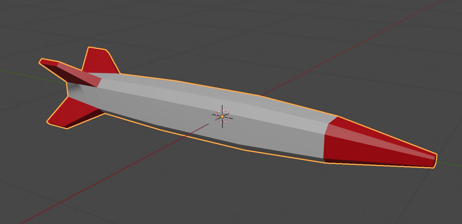
Creating a Missile
We made a simple missile in Blender and exported it as an FBX file and imported it into Unity. We then created and empty GameObject, placed the missile model under it in the hierarchy and created a prefab from them.
Once in the prefab folder, we edited the prefab and added a ConstantMovement behaviour and a DestroyOnDistance behaviour. This makes the missile fly and eventually destroy itself.
Shooting
Controls
First we had to edit our ShipControlls.inputaction in our Inputs folder by double clicking on it. We then added a new action of type Buttoncalled Shoot with a single Binding to the Spacebar on the keyboard.
We used the SaveAsset button on the dialog above to save the input actions.
In our code then in ShipController we added the following at the bottom of update:
    // Shooting
    if (_controls.Ship.Shoot.WasPerformedThisFrame())
    {
      Debug.Log("Shoot was pressed on frame " + Time.frameCount.ToString());
    }
This allowed us to see that the shoot command was being picked up with a message getting written to the console every time the spacebar was pressed.
What and Where
We added two new properties to ShipController:
  public GameObject MissilePrefab;
  public Transform MissileSpawnPoint;
The first is to store our Missile prefab and the second is to store a location under the ship where the missile can be launched from. To create this we added an empty called MissileSpawnPoint under Player in the scene and, in a side view, moved it down below the ship and towards the front of the ship.
We could then assign this and the missile prefab to the appropriate properties of ShipContoller attached to the Player object.
Launching a Missile
In PlayerController we swapped the call in Update() to Debug.Log() for a call to a new private function Shoot() which we also created, to look like this:
  private void Shoot()
  {
    // Create a missile at the missile spawn point
    Instantiate(MissilePrefab,
                MissileSpawnPoint.position,
                MissileSpawnPoint.rotation);
  }
Every time now that the spacebar is pressed, a missile is created below the spaceship and flies forward for approx. 8 seconds before destroying itself.
Rate Limiting
It’s unrealistic to be able to shoot missiles as quickly as we can hit the spacebar, so some idea of fire rate is useful. It’s easy to convert a rate into an interval, all you have to do is divide one by the rate to get the interval. For example, if the rate is 2 per second then the minimum interval between shots is 1/2 = 0.5 seconds. Similarly, if the rate is 10 per second then the minimum interval between shots would be 1/10 = 0.1 seconds.
We add a new property to ShipController called FireRate.
The first of these is the minimum interval between shots. We calculate if from the rate, as described above. Since we just need to do this once, we pop the code in Start():
The second private property stores the last time we fired a missile. We set it to a arbitrary large negative value so that at the start of the game it’s the same as if it’s been ages since we fired a missile, even though we’ve never actually fire one yet.
We can now check the time since we last fired a missile against the minimum time between shots in the Shoot() function:
  private void Shoot()
  {
    if (Time.time - _lastShotTime < _minTimeBetweenShots)
      return;

    // Create a missile at the missile spawn point
    Instantiate(MissilePrefab,
                MissileSpawnPoint.position,
                MissileSpawnPoint.rotation);

    _lastShotTime = Time.time;
  }
Getting the Code
All the code we’re made this year is on our GitHub. It can be found here. If you don’t have the latest version of our code before any session, use the green Code button on that page to get the “Download ZIP” option which will give you a full copy of all code we’ll be writing this year.
This week we continued writing the code to control our environment.
Creating a Random Piece of Environment
We started by adding a new function CreatePrefab() to EnvController.cs. It uses Random.Range() to pick a random prefab from EnvPrefabs and then uses Instantiate() to create a copy of that prefab in the scene. Here’s the first version we wrote:
  private GameObject CreatePrefab(Vector3 position)
  {
    // Pick a random prefab
    int numPrefabs = EnvPrefabs.Length;
    GameObject prefab = EnvPrefabs[Random.Range(0, numPrefabs)];

    // Create an instance of it
    GameObject go = Instantiate(prefab, position,
                                Quaternion.identity, transform);

    // Add DestroyAfterDistance to it
    DestroyAfterDistance dad = go.AddComponent<DestroyAfterDistance>();
    dad.Distance = 700.0f;

    // Add ConstantMovement to it
    ConstantMovement cm = go.AddComponent<ConstantMovement>();
    cm.Direction = Vector3.left;
    cm.Speed = 100.0f;

    // Return it
    return go;
  }
Note that CreatePrefab() takes a position to create the new instance at as an argument. It also returns the GameObject we created, which will prove useful later.
To make the code actually run, we added this to the Start() function:
CreatePrefab(Vector3.zero)
Vector3.zero represents (0, 0, 0).
We quickly found that this created our random piece of environment, but it wasn’t rotated the way we wanted. We updated CreatePrefab() as follows to correct that:
    // Create an instance of it
    Quaternion rotation = Quaternion.Euler(0, -90, 0);
    GameObject go = Instantiate(prefab, position,
                                rotation, transform);
We create a new variable rotation which represents a rotation of -90 degrees around Y (the vertical) and then use it in the call to Instantiate() instead of Quaternion.identity.
Initial Environment Setup
When the game starts, we want to have the ground under and ahead of the spaceship filled in. To do this, we first create some new class properties:
  public GameObject[] EnvPrefabs;
  public float Spacing = 100.0f;
  public float Speed = 50.0f;
  public int Count = 6;

  private Vector3 _spawnPoint;
  private GameObject _lastGo;
There are three new public properties. Spacing represents the size of each environment piece. Speed is the speed we’d like everything to move at. Count is how many environment pieces to have visible at a time.
There are also two private properties. _spawnPoint represents the place we’d like new pieces of environment to appear. _lastGo stores the last piece of environment we created.
In Start() we initialise _spawnPoint() like this:
    // Calculate the spawn point based on spacing and count
    _spawnPoint = Vector3.right * Count * Spacing;
We’ll use all these properties eventually. For now, we just write a new function Preload() and call it from Start() instead of CreatePrefab().
  private void Preload()
  {
    for (int i = 0; i < Count; i++)
    {
      Vector3 pos = Vector3.right * i * Spacing;
      _lastGo = CreatePrefab(pos);
    }
  }
This function just loops for Count times, working out a new location to place the environment piece and calling CreatePrefab(). It stores each prefab as we create it in _lastGo. When we run, we see the environment under the ship, but once it passes it’s gone and no more is created.
Having EnvController Control the Speed of the Environment Pieces
Instead of having each environment piece we create have it’s speed set and constant, we decided to link it to the EnvController. To to that we create a new class called MoveWithEnvironment.cs. It looks like this:
using UnityEngine;

public class MoveWithEnvironment : MonoBehaviour
{
  public EnvController EnvController;

  // Update is called once per frame
  void Update()
  {
    if (EnvController == null)
      return;

    transform.position = transform.position +
      (Vector3.left * EnvController.Speed * Time.deltaTime);
  }
}
It’s very similar to ConstantMovement but it always moves towards Vector3.left and it takes speed from the EnvController. This allows us to vary the speed in the EnvController and have all environmental pieces immediately react to that. We need to add this, instead of ConstantMovement, to our newly created piece of environment in EnvController.CreatePrefab():
    :   :    :
    // Add DestroyAfterDistance to it
    DestroyAfterDistance dad = go.AddComponent<DestroyAfterDistance>();
    dad.Distance = 700.0f;

    // Add MoveWithEnvironment to it
    MoveWithEnvironment mwe = go.AddComponent<MoveWithEnvironment>();
    mwe.EnvController = this;

    // Return it
    return go;
}
All the code relating to ConstantMovement is replaced with code relating to MoveWithEnvironment instead. We assign the special variable this to set the EnvController property in MoveWithEnvironment.
Creating More Environment as We Need It
To create environment as we need it, we added code to Update() as follows:
The code first checks to make sure that _lastGo has been set. If it has, it worked out how far the last piece of environment has moved from the _spawnPoint. If it’s equal to, or greater than, the spacing then we make a new piece of environment.
Now, as pieces of the environment move towards Vector3.left new ones are created as needed in front of our spaceship.
This code almost works great, but there’s one thing – there’s clearly gaps between the pieces of environment some times. This is because it’s not likely that on a specific frame the environment piece will have moved exactly Spacing meters. It will usually have moved a little more, hence the gaps.
Next session, we’ll correct for this.
Getting the Code
All the code we’re made this year is on our GitHub. It can be found here. If you don’t have the latest version of our code before any session, use the green Code button on that page to get the “Download ZIP” option which will give you a full copy of all code we’ll be writing this year.
This week we took our Blender creations back into Unity. We started with the same file, ShipsAndEnv3.5,blend, which can be found here on our Teams site (for site members only).
Export from Blender
Blender offers extensive export options and we quickly ran through the list. The one we’re going to use is FBX. It’s a widely used format, well supported in lots of 3D software, with good material and animation support.
To export the file, we made sure all object were unhidden, and chose File|Export|FBX. We left all the options as-is except the “Apply Transforms” option, which we selected. This option has a warning next to it, as it doesn’t work with animations, but that doesn’t apply to us here.
The resulting FBX file was saved to the same folder as our BLEND file.
Import into Unity
To import the FBX file into Unity, we created a new folder called “Model” and dragged the FBX file from Windows Explorer/macOS Finder into it.
We decided to extract the materials from the file. This will allow us to change them in Unity. To do that we selected the FBX in the Model folder in Unity and in the Inspector window, went to the Material tab and chose “Extract Materials”. All the materials in the FBX were then extracted as Unity materials in the same folder as the FBX file.
Prefabs
We then wanted to break apart the combined FBX file into it’s separate parts. To do that we first created a blank scene and dropped the model from the “Model” folder into the Hierarchy window. We checked the Inspector window to make sure it was positioned at (0, 0, 0) and adjusted it if needs be.
Note that Unity showed the model coloured blue in the Hierarchy. This means it was treating it as a “Prefab”. A prefab in Unity is just a collection of GameObjects and components that are treated as a template. It’s easy to create copies of them at run-time.
We want prefabs of all the things in the FBX file, not the FBX model itself. To separate out the bits from the FBX model, we right-clicked on it in the hierarchy and chose Prefab|Break Apart Completely. Not much obviously changed except everything in the hierarchy turned black, indicating it was no longer a prefab, just normal objects.
We then created a new folder called “Prefabs” and dragged everything inside the FBX model (but not the FBX model itself) into it. That’s all you have to do to make something you already have in a Unity scene into a prefab, drag it into the Project window. Now we can create copies of all these objects at run-time very easily.
Adding our Ship to the Scene
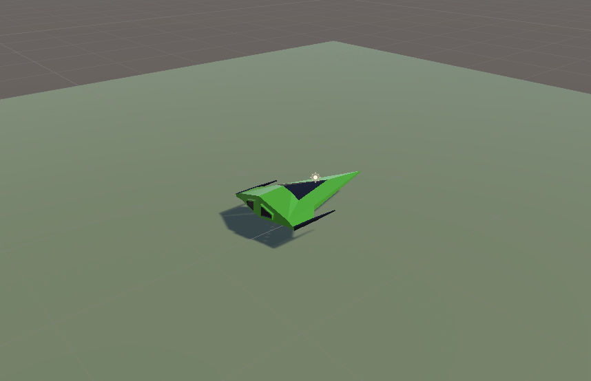
To add our ship to the scene, we dragged the Ship prefab from the Prefabs folder and dropped it onto the Player gameobject in the Hierarchy. The Ship model was then a child of the Player object. We needed to rotate the Ship by -90 around the Y axis to make it point in the correct direction. We also set the scale of teh Plater object to (1, 1, 1) and removed the Mesh Filter, Mesh Renderer and Box Collider components from Player, as these were no longer needed.
Our game looks better already with a ship model rather than a flying mattress!
Some Test Code
We tested two simple components on a test cube added to the scene. One which created constant movement in a particular direction and the other which deletes the attached gameobject once we’ve traveled a set distance from where we started.
The first of these, ConstantMovement.cs looks like this:
using UnityEngine;

public class ConstantMovement : MonoBehaviour
{
  public Vector3 Direction = Vector3.forward;
  public float Speed = 10.0f;

  // Update is called once per frame
  void Update()
  {
    Vector3 offset = Direction.normalized * Speed * Time.deltaTime;
    transform.position = transform.position + offset;
  }
}
Two public variables define the direction and speed respectively. In Update() we calculate how to move this frame by multiplying the normalised version of the Direction (normalised meaning the length is set to 1) by the speed and Time.deltaTime (the time since the last frame). We then set a new value for the position by adding this offset to the previous position.
The second DestroyAfterDistance.cs looks like this:
using UnityEngine;

public class DestroyAfterDistance : MonoBehaviour
{
  public float Distance = 10.0f;

  private Vector3 _initPos;

  // Start is called before the first frame update
  void Start()
  {
    _initPos = transform.position;
  }

  // Update is called once per frame
  void Update()
  {
    Vector3 offset = _initPos - transform.position;
    float offsetDist = offset.magnitude;

    if (offsetDist >= Distance)
    {
      Destroy(gameObject);
    }
  }
}
It just has once public variable, the distance the GameObject is allowed to travel. It also has one private variable, set in Start(), which stores the initial position.
In Update() we check how far we’ve travelled by getting the vector difference between the start position and our current position and then getting it’s magnitude (aka length). This tells us how far we have moved. if this distance is greater than the the specified Distance, we call Destroy(gameObject) thereby destroying the GameObject this component is attached to.
Getting the Code
All the code we’re made this year is on our GitHub. It can be found here. If you don’t have the latest version of our code before any session, use the green Code button on that page to get the “Download ZIP” option which will give you a full copy of all code we’ll be writing this year.
This week we completed our ship from the previous week by adding some materials. Materials are what provides colour to models.
Out model, by default, contains a single material slot. This default material is a grey material and because there’s a single slot, it’s applied to all faces.
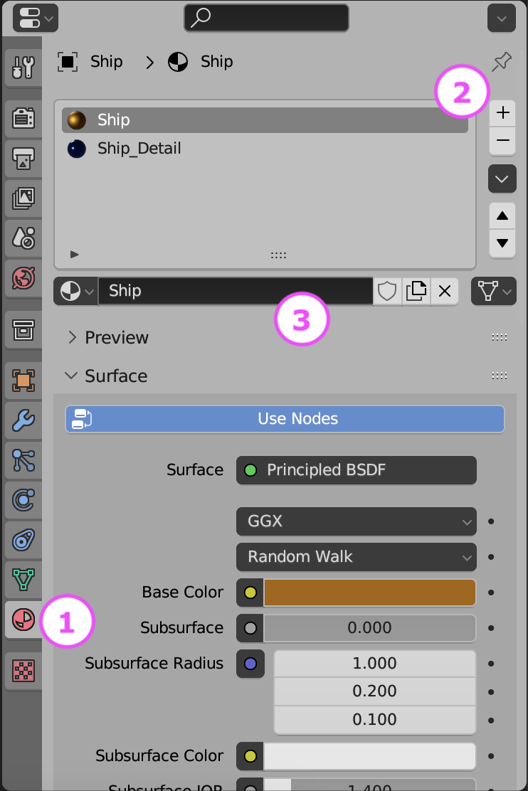
To start colouring our model we went to the material properties panel on the right-hand-side of the screen. It has a red circular icon as seen at (1) below.
We removed the default material slot by using the – key at (2) above then then added two new materials, called Ship and Ship_Detail by pressing + at (2) to make two new material slots and using the “New” button at (3) when those empty slots where selected to actually make a new material.
The default material component has a lot of inputs, but we can ignore most of them for now. The most important ones are:
Base Colour: This is the main colour of the material
Metallic: How much like a metal the material is. Although a slider, its normally to be either zero (not a metal) or 1 (a metal) rather than anything in-between.
Roughness: How smooth or rough the material is. Will greatly impact how light reflects off the object. Metallic materials with very low roughness look mirror-like.
We set Ship and Ship_Detail with contrasting colours, metallic finish and low roughness.
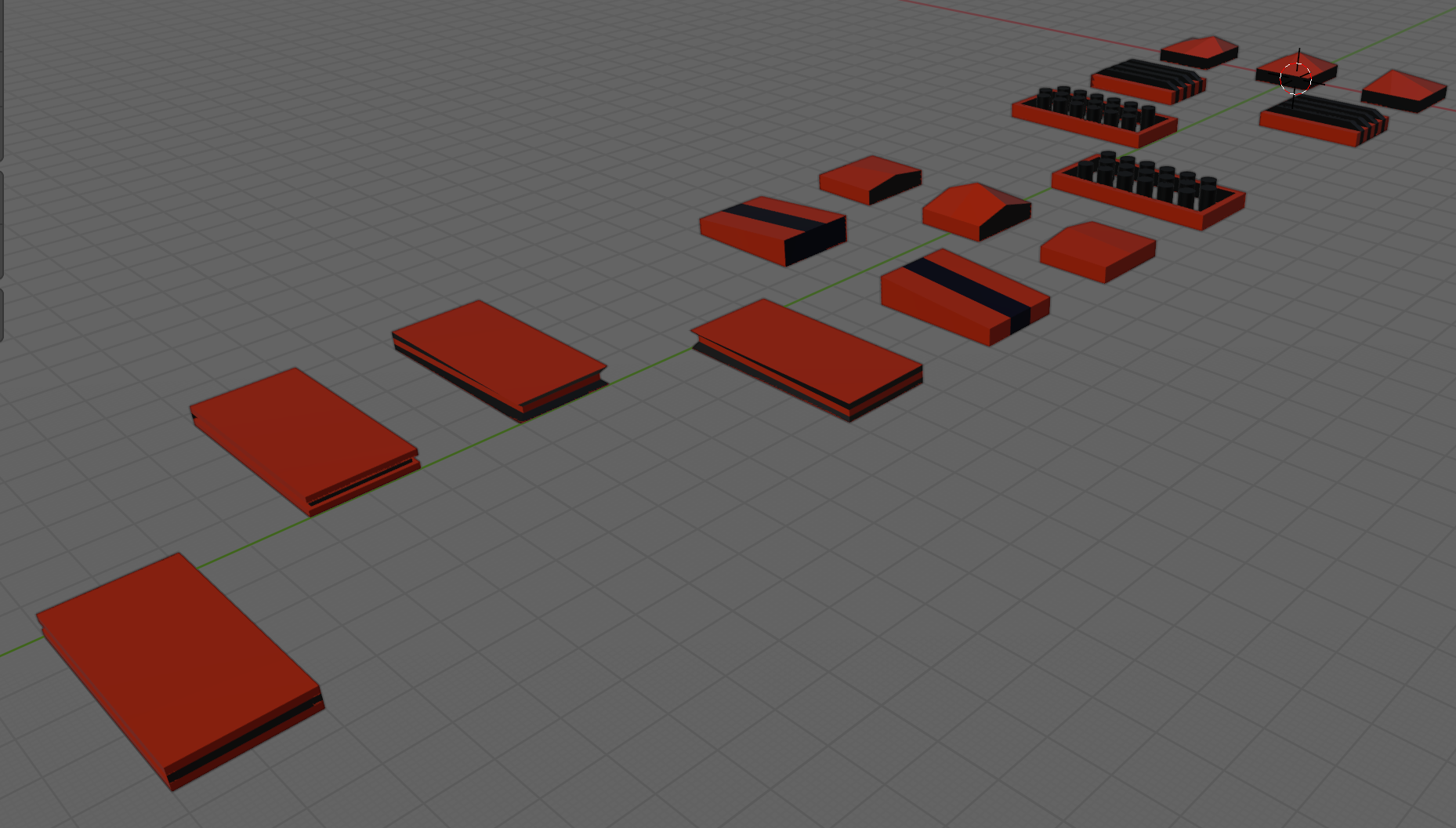
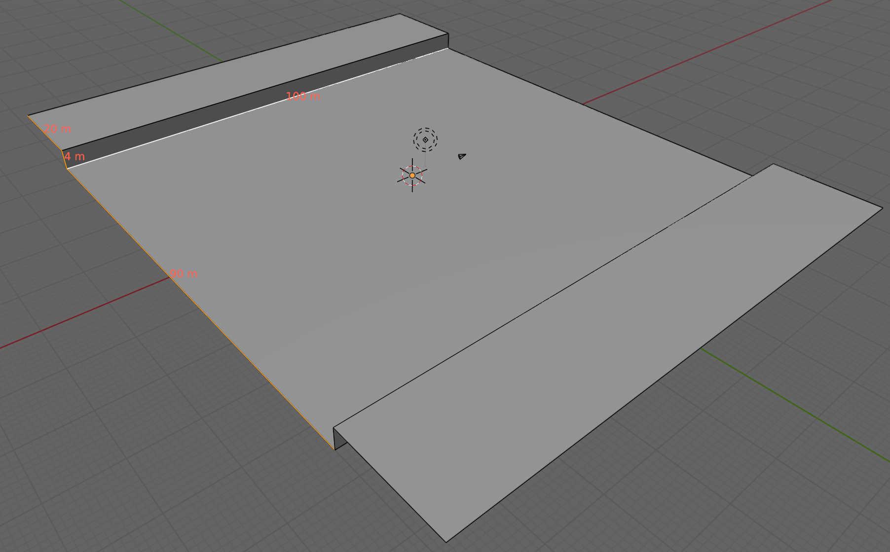
Environment
We are going to create loads of environment sections that snap together. The follow the basic pattern show above. A flat area 90x100m in size, with a vertical edge 4m high and a 20m flat area beyond that. We can add any embellishments to the raised flat area on the sides, so long as they’re not too high on the side facing the camera. We don’t want to obscure the ship.
Like the ship, we created two contrasting materials for the environment, one dark as a base and one bright as a contrast colour for details.
Getting the Model
The Blender model for this week can be downloaded from our Teams site here.
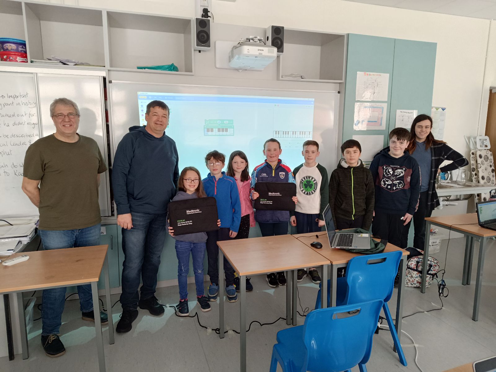
We are very grateful to the Medtronic Foundation, through Medtronic employee and mentor Declan Fox, for the donation of several laptops to CoderDojo Athenry. Our loaner laptop program helps those who cannot otherwise afford a laptop to attend CoderDojo Athenry. Keeping CoderDojo Athenry free to attend and as inclusive as possible is always one of our key aims.
The Medtronic Foundation partners to improve health for underserved populations, as well as supports communities where Medtronic employees live and give. They empower Medtronic employees to positively impact local communities by leveraging their skills, time and resources. If you’d like to read more about their work you can find their webpage here.
This week we took our cube and made it vaguely more spaceship-shaped by moving it up to (0, 2, 0) and resizing it to (5, 1, 4). We also took our ground plane and scaled it to (10, 10, 10). Now it looks vaguely more like a flying craft than before!
The ship controls still work as before. WASD move the ship horizontally over the ground and there’s no vertical movement. To make it look more like a flying craft, we’d like it to bank (aka. tilt over) as it moves horizontally. That’s going to take a bit of figuring out.
Angles in Unity
Let’s take a little aside to talk about angles in Unity.
In the Unity Inspector we see three numbers for a transform’s rotation. These numbers represent rotations around the X, Y and Z axis respectively. This way of storing a rotation is known as “Euler angles”. It seems simple and straightforward and, if you’re rotating around just one of the X,Y or Z axes, it is, but for complex rotations it actually has a lot of problems. The order in which you apply the rotations matters. If you rotate first in X then Y and the Z, you get one orientation, but choose a different order and you’ll get something different. It’s ambiguous.
Look at these two boxes. Each are rotated by 90degrees around the X and Z axis but in a different order. They end up in completely different orientations:
Rotations internally in Unity are stored using a special variable called a Quaternion. Euler angles can easily be converted to Quaternions and back again. Quaternions store the axis that the object rotates around and the amount of the rotation. It’s completely unambiguous with no order to worry about.
When we code, we use Quaternions for rotations because that’s what Unity uses.
Variables for Ship Tilt
In ShipControls.cs we add two variables TiltSpeed and TiltLimit to control banking. TiltLimit represents the amount of degrees we’re going to bank as we move horizontally and TiltSpeed is how quickly we can change angle. We don’t want the craft immediately going from tilting one direction to tilting the other – we want a smooth change of rotations. That will look a lot better.
  public float TiltSpeed = 10.0f;
  public float TiltLimit = 10.0f;
Because these are public properties, we see them appear in the inspector for Ship Controller.
Determining What Tilt We Should Have
Tilt is dependent on the user input. If the user is pressing right, we should be titled to the right. If the user is pressing left, we should be tilted to the left. If the user isn’t pressing left or right, we should be level.
In the Update() function in ShipControls.cs we add this code near the top:
So depending on user input, tiltTarget will either be 0, TiltLimit or -TiltLimit (note the minus). We then turn this into a Quaternion representing this amount of a rotation around the X axis.
Moving Smoothly Between Rotations
How do we move smoothly between two rotations, namely the rotation we’re at and the rotation we want to be at?
There’s a general concept called “linear interpolation” for finding a value some proportion of the way between two other values. Let’s imagine a trivial example; if our numbers were 0 and 10 then the number 50% of the way (aka. half) between these would be 5. In Unity linear interpolation is known as “Lerp” and it can be used not just for simple numbers but for Vector3’s (representing positions and directions) and Quaternions (representing rotations) too.
For Quaternions, Unity has a special “Lerp” that works really well for rotations called Quaternion.Slerp(). “Slerp” stands for Spherical liner interpolation. Not a function name you’ll quickly forget. So to “Slerp” between the angle we’re currently at and the angle we’d like to be at, we need to know what proportion of that change we can make this frame. Here’s how we calculate that proportion:
Find the angular different between the rotation we’re at and the rotation we’d like to be at
Calculate how long, given the speed we’ve specified for changing angle, it would take to fully make that change in rotation
Calculate, given the time since the last frame, what proportion of that change we can actually make (it will be just a small bit of the change).
Finally we actually set the transform’s rotation using Slerp(), the rotation we’re at, the rotation we’d like to be at and the proportion of the change that we’ve calculated:
Testing the ship control code we found that good values for the variables were as follows:
Move Speed
50
Tilt Speed
100
Tilt Limit
30
We also noted that any values entered in the inspector override defaults in the code.
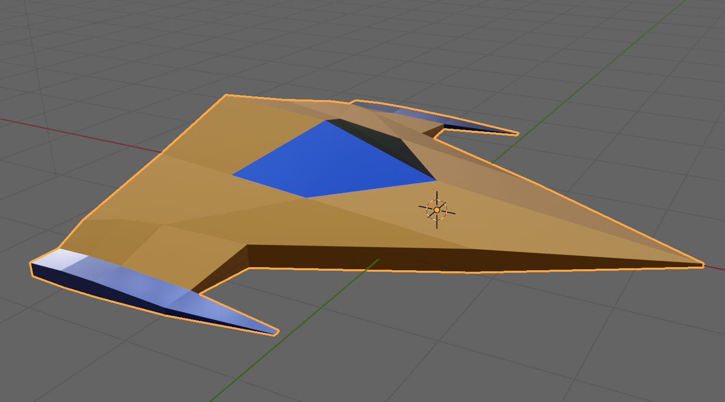
Simple Blender Spaceship
We started on a simple spaceship model in Blender, using the proportions of our cube in Unity as a guide [5m x 1m x 4m].
This was mine, but everyone had their own take. If anyone wants to download mine, it can be found here on our Teams site. If you’re not a member of our Teams site yet, get in touch to be added.
When we return after our break, we’ll look to texture this model and export it from Blender and import it into Unity.
Getting the Code
All the code we’re made this year is on our GitHub. It can be found here. If you don’t have the latest version of our code before any session, use the green Code button on that page to get the “Download ZIP” option which will give you a full copy of all code we’ll be writing this year.